The one where Lewis totally, irreversibly loses the plot
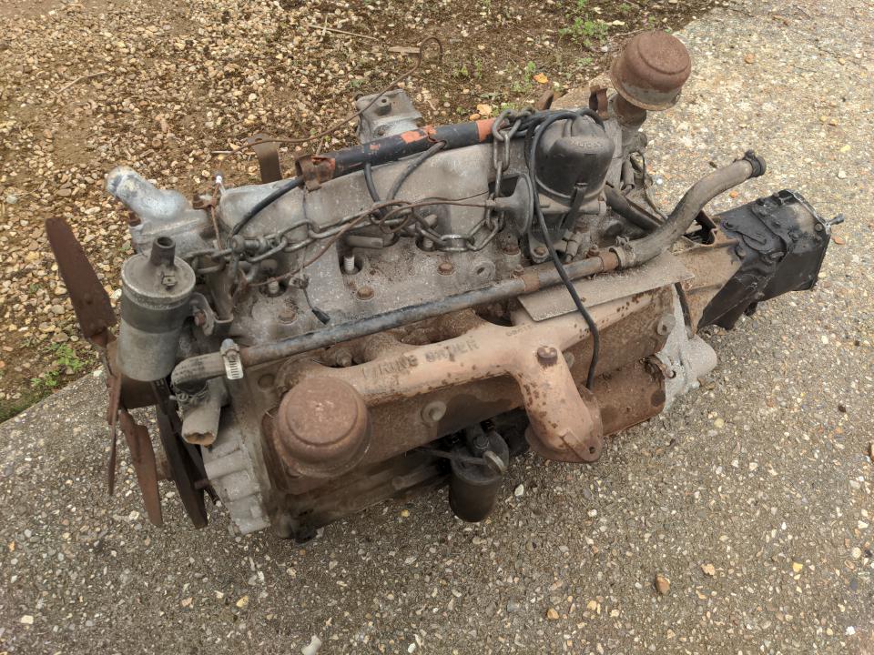
This was my Rover P5's engine.
You'll notice that it's not in the Rover P5.
So, the workshop build was completed, giving me a much nicer space to work in. The Mazda 323 GTX was fully someone else's problem while the engine is (still) being rebuilt. And some time ago I made some major life changes to give me more time and motivation; it worked! Which meant I could finally get back to the Rover P5, for which there are thousands of pounds worth of parts in storage to fit, and a list of jobs that'll keep me out of trouble for the foreseeable future. And I found myself procrastinating, again. Why?
Someone wise once told me that when I find myself procrastinating, I need to look for the fear. I think one of those fears is that I have seen some really nicely-done Rover P5s, and I doubt I will ever be able to do one as well as those. There's a fear of being judged by all the people that build all those perfect P5s. Half of that doesn't matter (it doesn't need to be perfect) and the other half is mostly something I made up (there are so very few judgy people in the classic car world and I'm actually thick-skinned faced with actual criticism rather than imaginary criticism anyway).
What I also found out was: When finished, I just wouldn't find the P5 fun to drive.
It's a beautiful car, maybe one of the most beautiful cars ever made. This one in particular, in this colour, is so beautiful that I was forced to impulse-purchase it. And yet, it has an engine designed shortly after World War II, a carburettor, a distributor with points, and 115 horsepower. The horsepower number sounds OK, but it is in a car weighing 1700 kilograms. It is substantially slower than my totally-standard 1.4 litre Ford Fiesta from 2004, even if you forget the fact that my Fiesta can corner and a P5 can't. Or that my Fiesta has actually worked every day, where a car with a carb and a distributor with points is a lottery.
A 3-litre Rover P5 is not fun to me, and I live my life one fun at a time, or something.
Anyone sensible would have sold the car at that admission-to-self. Actually, anybody sensible would not have bought impulse-purchased a non-working car for £3500 unseen over the Internet, so wouldn't reach this point in the first place. Because I'm not sensible, I decided to start a new plan: make a Rover P5 fun to drive.
I actually had several ideas. One was to develop fuel injection & electronically-controlled ignition for the IOE engine, to at least make it reliable and probably get a few more horsepowers out of it. That would open up more options, like shoving a massive turbo onto it for the lolz, and well, if that idea sounds insane that's why I didn't do it.
So, what else? Rover V8? 2JZ? K20???
They all have their merits. And yet, those are all petrol engines. Any discussion of drivetrain swaps in classic cars must eventually face the spectre of electrification.
Electric means 100% torque at zero RPM, fewer moving parts, near-silent; it's, like, the future, man. And though some consider it sacrilege to electrify a classic car, it can be argued that changing an old, unreliable, underpowered petrol engine to a modern, reliable, much more powerful one is changing the character of a car every bit as much as electrifying a car is. And nobody but the dullest of rivet-counters objects much to all the mad engine swaps out there; why object, then, to electrification?
But there's more. We all know that petrol engines pollute. Some would argue that, whatever the historic value of these old cars, an internal combustion engine in a classic car in The Current Year is like painting an historic house with lead paint, heating it with trees felled from old-growth forests, and emptying a chamber pot from its windows onto the street. Such a thing may have been a grim necessity in the past; doing it today when we have clearly better and cleaner options is entirely irresponsible. And, honestly, it's very hard to argue with that.
And that is why I bought
a Corvette engine, because fuck 'em.
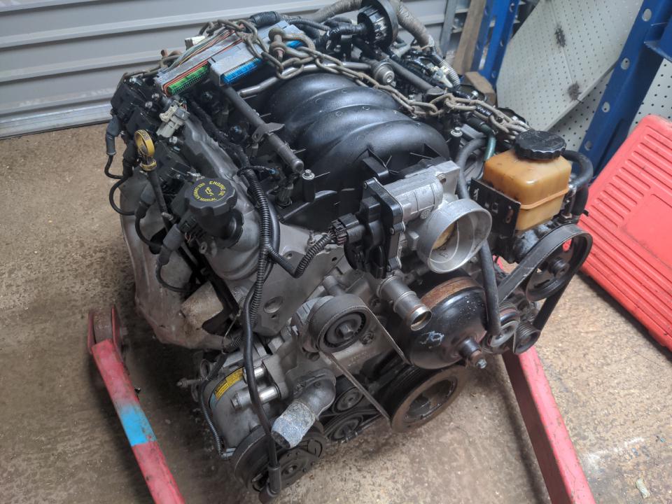
This is the Chevrolet LS1, a 5.7 litre V8 petrol engine with about 350 horsepower and over 350 lbs/ft of torque, and an aftermarket that will take them to arbitrarily large power numbers. And it makes cool V8 noises! Now we're talking!!
This is not another dumb impulse purchase (he said with a straight face) but the product of a lot of thinking. I wanted reliable power in a compact package that had some hope of fitting in the P5.
I needed something well-documented; "LS1 into a Rover P5" might not have been done before, but "LS engine into something that shouldn't have an LS engine" has been done probably thousands of times. And anything you are thinking of doing with an LS1, the fine folks over at the LS1Tech.com forums have probably already done it five times and found out which of those five ways works best and which four don't.
I needed something somewhat modern; no LS engine has a distributor, and they definitely do not have a carb, which would allow me to preserve my unbroken 41-year streak of not dealing with carbs. (Yes, I would rather re-engineer a car entirely rather than ever deal with bloody carbs and this is literally what is happening here.)
It is a simple engine, compared to other modern engines with the same power figures. I reckon I could hold one in my head. Simplicity means less to go wrong, and simplicity means that if it does go wrong it's straightforward to fix. Simplicity also means that they could build them cheaper, and make up the difference with displacement.
It's kind of cheap. There are no scrapyard LS engines in England; this cost me nearly £4000 and it had to be shipped from Ireland. But if you price it against any other 350 horsepower engine it's not that bad. Sure, everyone's getting 350+ out of their K20s these days - but you won't get a K20 pushing out that kind of power reliably for £4k. Or maybe I could probably pick up one of the German V8s for that money - but then that would be a monstrously complicated engine with no substantial after-market. Or I could pick up a JZ - for substantially more money, and complexity, and that still wouldn't push 350 horsepower without modification. (This was actually my original plan. My brother talked me out of it. I am glad he did, and not just because that means losing the next several years of my life to this is not at all my fault.)
I used to hate the saying there's no replacement for displacement. You probably won't find me using it again after this very paragraph, in fact. But I have to admit there's something to it. For reliable power at a given price point, sometimes it's best to throw a bunch of unsophisticated cubic centimeters at the problem. "Quantity has a quality all its own", as Stalin once said while trying to find positive things to say about my welding. Or, "when in doubt, use brute force".
And that is how Lewis convinced himself that buying a 5.7 litre V8 was a good idea! So...
Does it fit?!
As if I'd ask that sort of question before spending all of my money on an engine! But I had a hunch that it would. Its 5.7 litre displacement seems ludicrous to anyone whose patriotism includes no eagles, but it's actually a remarkably compact engine. It's substantially smaller in most dimensions than a Rover V8, and we know a Rover V8 fits in a Rover P5. But measurements can lie; I wouldn't know for a fact that it fits until I shoved it in the engine bay and saw what it collided with.
What I didn't feel like doing, though, was lifting 215 kilos in and out more than once, because setting up the engine crane every time would be effort. Which is why I bought another LS engine!
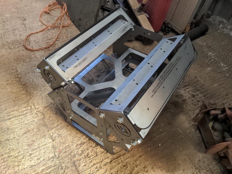
The eagle-eyed among you will notice that this isn't really an LS engine. It's the wrong colour! This is, instead, a mockup engine, or as I like to call it, a stunt engine. It replicates all of the critical dimensions and mounting points of a real LS engine. My one even has fake cylinder heads! And it weighs like 8kg, or 15kg with the "heads", which is a weight nobody minds lifting in and out of a car. You can get one at Speedway Motors in the US. (Their website plain doesn't work with non-US delivery addresses and telephone numbers though; you'll have to give them a phone call if you're outside the US, and brace yourself for the shipping cost.)
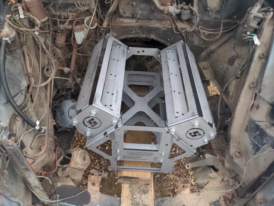
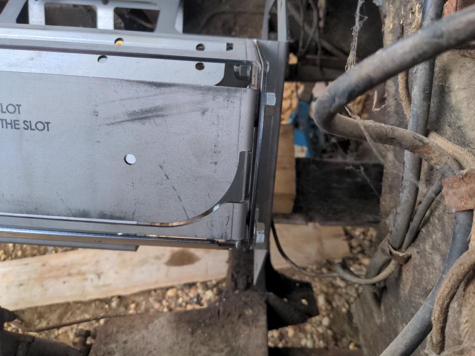
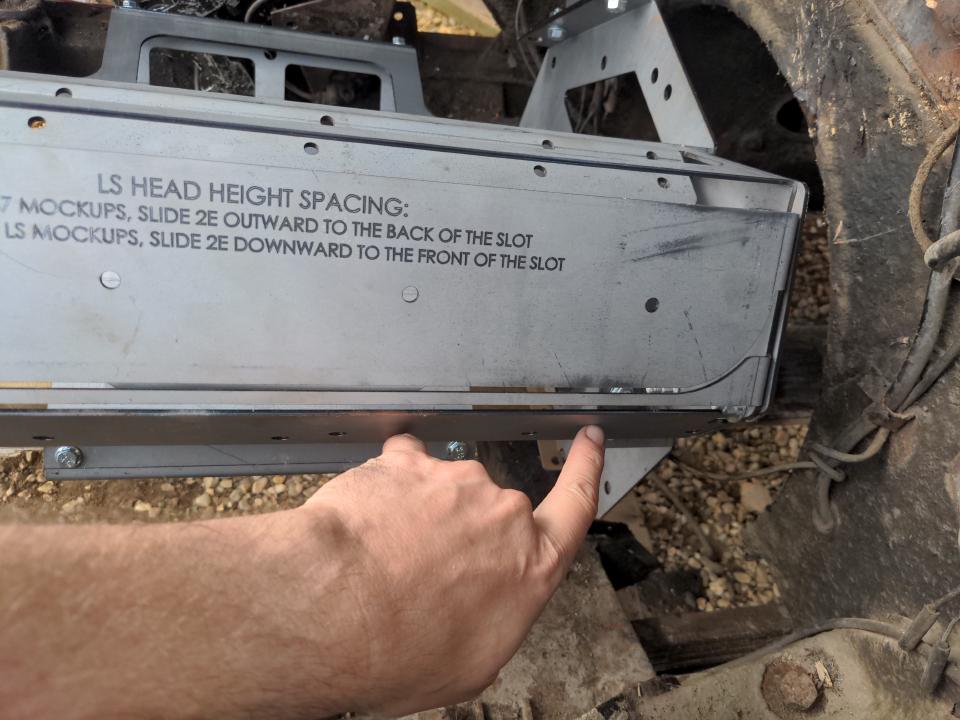
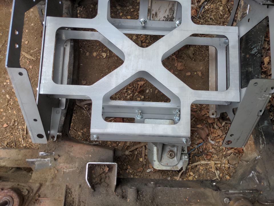
So, I dropped the stunt engine into the P5's engine bay, in about the same place that the original IOE engine sat.
Let's talk first about what "fits" means. What that really means is that it doesn't hit anything that I want it to clear. There are some things that are non-negotiable. It can't interfere with any part of the steering. I don't want to chop out the front crossmember. I don't want to cut into the bulkhead. I don't want to redesign the suspension. I don't want to have a bulge in the bonnet, because that would look silly. Anything else - especially adding metal to the car - is up for grabs.
As you can see, there's miles of vertical space there, and no clearance problems around the heads. Let's look at the air conditioning pump.
Acres of room there, because I threw the air-con pump onto the scrap pile (not gonna need it, and saves 8kg), so there's nothing to clear. Woohoo!!
Let's look at the other side.
The big mount on the right-hand side is one of my old engine mounting points; that's going to get chopped off. The small brackets at the front are for the radiator or something, I forgot. Don't worry about those. They're in the way, but they can be anywhere on that front crossmember, and anyway nobody said that the radiator must be at the front of the car.
:)
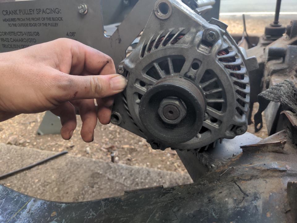
Still, there's a possibility that the alternator will not clear the front crossmember. It's going to be tight. Even if it fits, it might be a pain to get in and out. It might necessitate a more compact alternator, and if that doesn't work I can mount the alternator at the top right of the engine as the LS-engined trucks have it. There's some possible solution for it out there even if I don't know what that is yet, so let's call that OK.
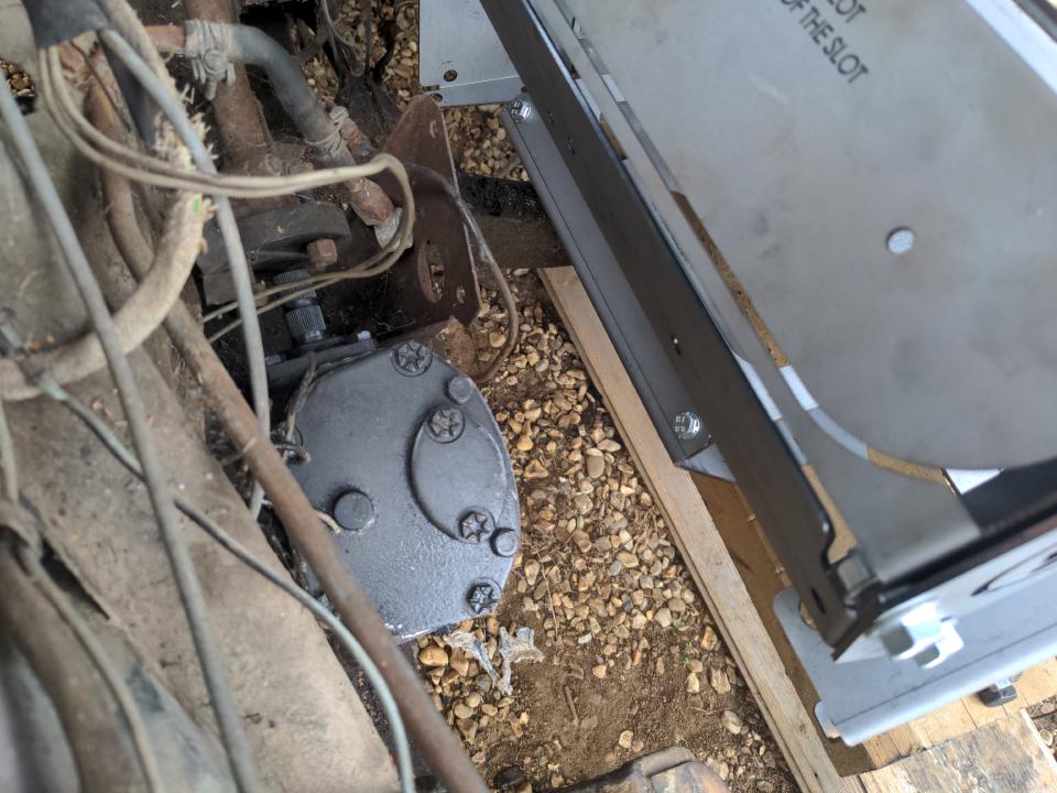
It's a bit tight around the steering box and somewhat less tight on the steering relay on the other side. Tight, but some design of engine mounting won't conflict. I can fabricate around this - run mounting rails from the rear to the front - in a way that'll allow me to get the steering components in and out.
And there's enough room at the back that I'll be able to unbolt the engine from the box with less hassle than the original engine! But while we're looking at the back...
No possible design of sump is going to clear that rear crossmember. This crossmember is negotiable though; it needs to be more or less there, but it doesn't have to look like this. It can plausibly be dropped lower and I'll pretend that this isn't going to result in any ground clearance issues.
My brother has a way of asking the obvious questions that I did not think of, such as...
And well, yes, I can.
So, an LS engine fits in a Rover P5, for some value of "LS engine" and "fits". With that point proved, I could drop the front subframe.
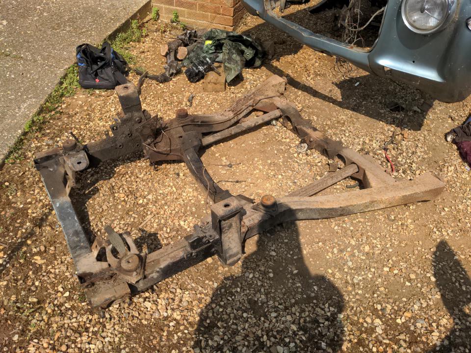
This was easier than expected. The six bolts that held it in actually came undone, perhaps because of plenty of penetrant applied in the days before. The only other things in the way were the old over-complicated handbrake mechanism (which is going to be replaced by something much simpler when that comes around), an earth strap, and a brake line, all of which were swiftly defeated by an angle grinder.
With the subframe on the floor, I could take a look at the original engine mounts. I said "Corvette engine" earlier because it is, but it was also fitted in many other cars, and I think these are Pontiac GTO mounts (which obviously implies this engine came from a GTO, and not a Corvette). With those bolted to the stunt engine, I could see that re-using them is somewhat plausible.
But that is without the engine at the correct height relative to the subframe; they're both sitting on the ground.
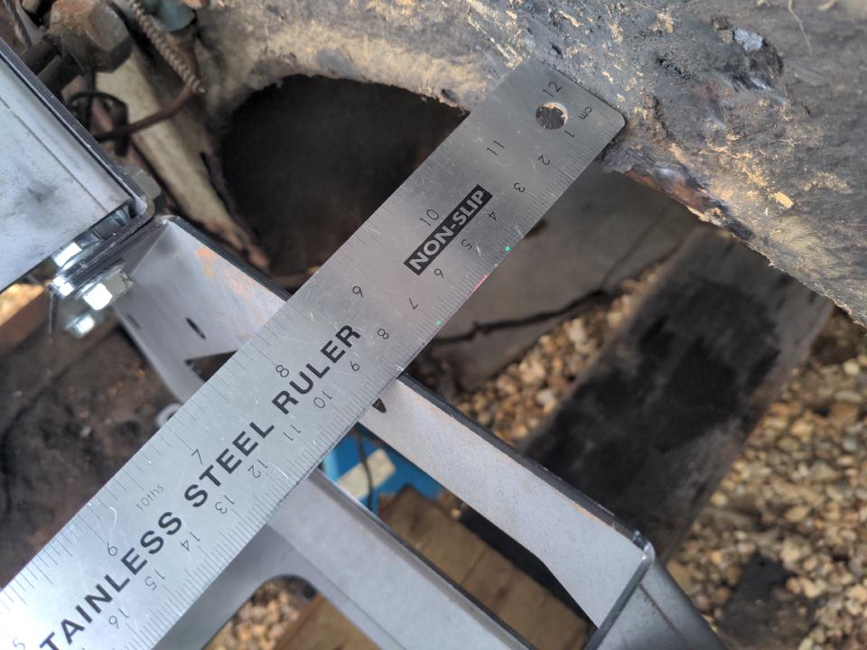
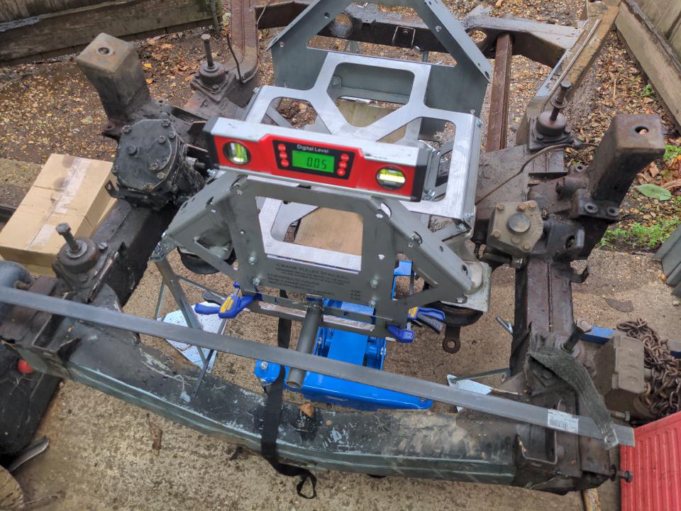
What is the correct height and location of the engine, though? I actually decided on this early on, before the old engine came out. It was to copy the forwardmost point and the crank centreline of the P5's engine. The engine is exactly central in the subframe. The very front of the vertical centre of the front pulley is 160mm from the deepest point of the dip of the front crossmember, with the front face of it sitting exactly in the fore-aft centre of that crossmember. The engine tilts back at an angle of 3 degrees. That, I decided, will be the position of the new engine; it is as good as any.
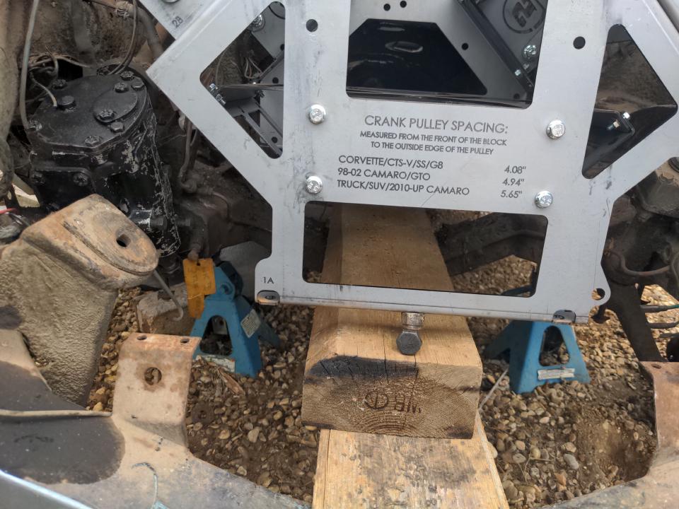
But to get the stunt engine in position on the subframe, how am I going to measure those dimensions relative to the front face and centreline of the front pulley, when my stunt engine does not have a front pulley? The answer, obviously, is to fit a front pulley to it. Here's what that looks like.
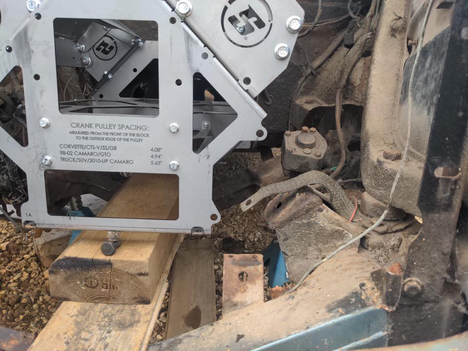
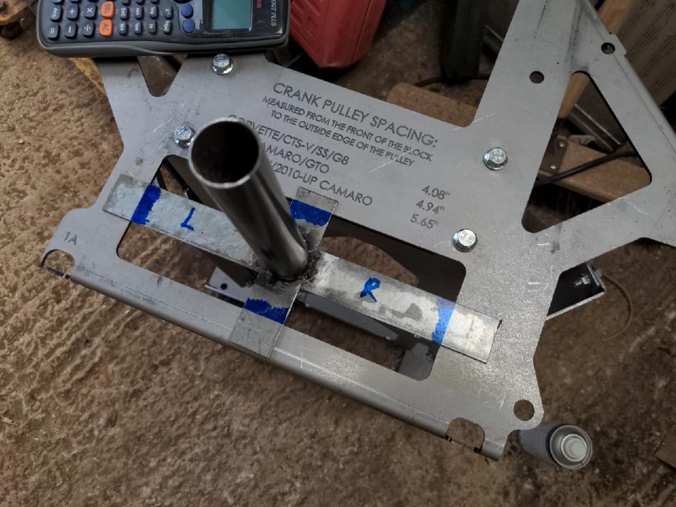
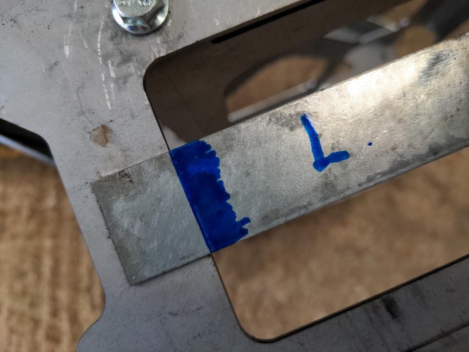
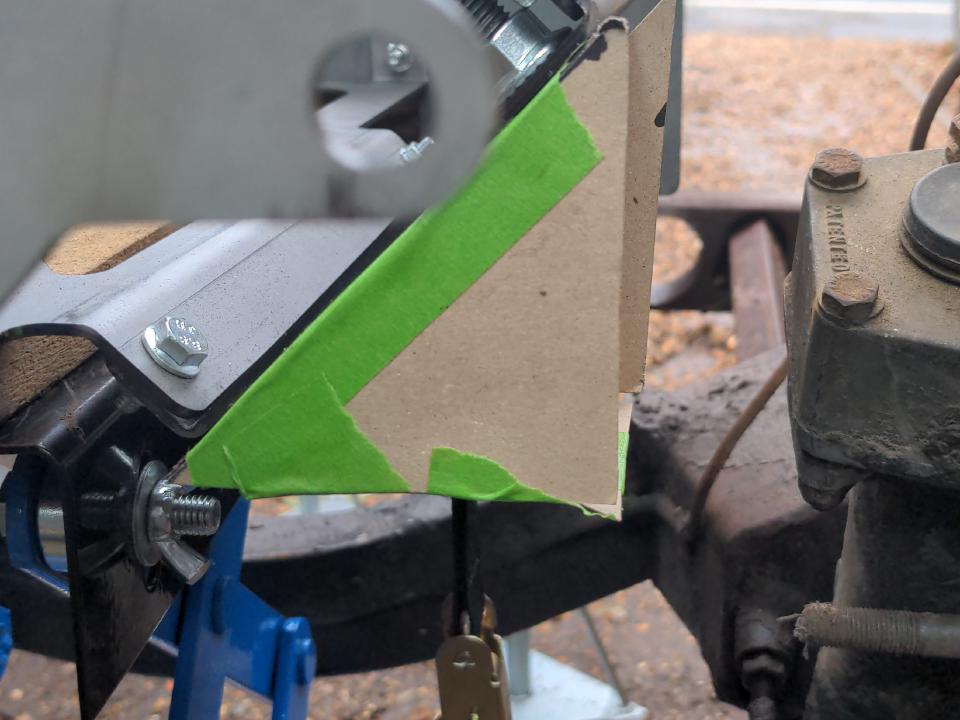
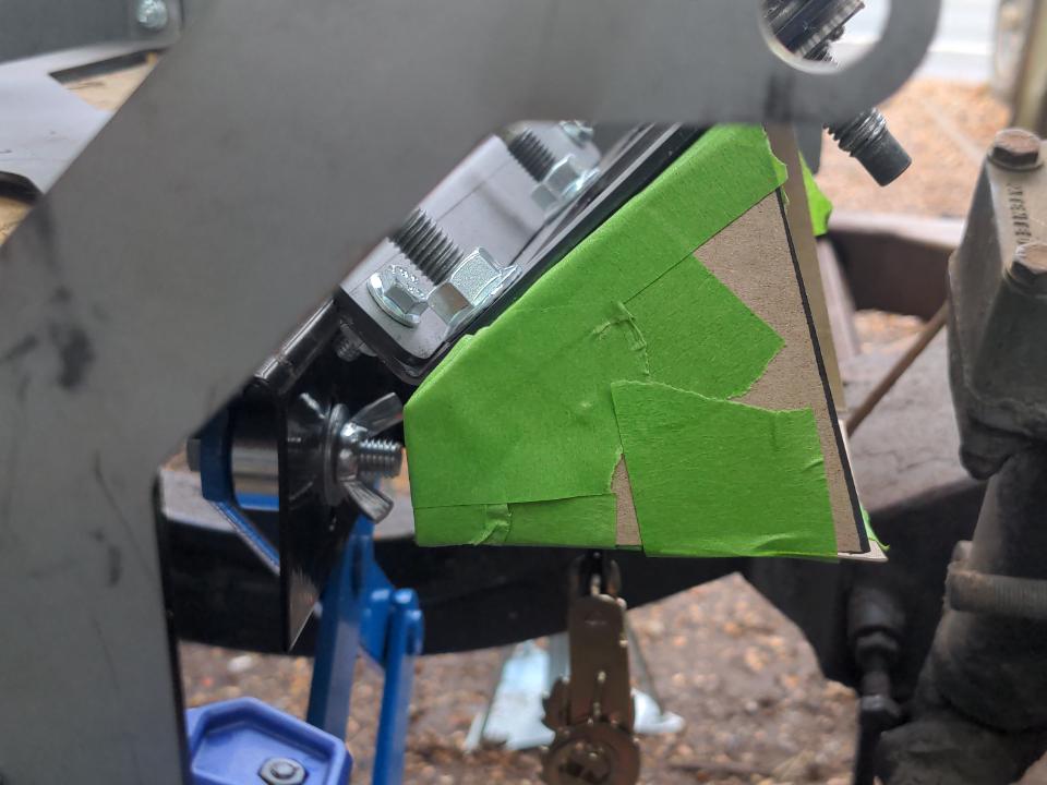
The eagle-eyed among you will notice that this isn't really an LS1 front pulley. It's the wrong colour! This is, instead, a mockup pulley, or as I like to call it, a stunt pulley. I don't actually need a whole front pulley; I need something to mark out the centreline of the crank and the stick-out of the real pulley. So I welded some shit together and came up with this. The centre of the rectangular cut-out on the front of the stunt engine corresponds with the crank centreline of the LS. After I positioned it as precisely as I reasonably could, I marked some sharp lines with a paint pen on the stunt pulley. When all four of these markings are lined up with the edges of the rectangular cut-out, like this...
...I know that the stunt pulley is exactly where it needs to be. This saves a lot of tedious measuring (it took 15 minutes to line this up perfectly to make the markings) and it's easy to validate with an eyeball that it hasn't shifted anywhere.
Anyway, let's get the fake pulley onto the fake engine, put it on the subframe and see how it goes.
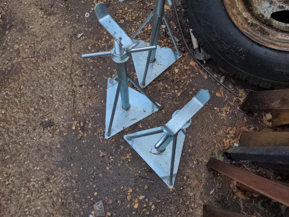
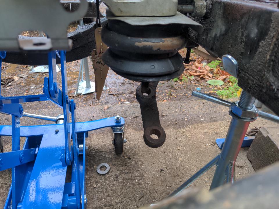
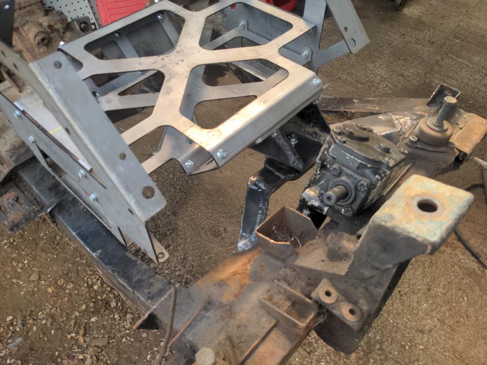
To do this, I bought these cheap adjustable caravan stands to hold the subframe up to a working height...
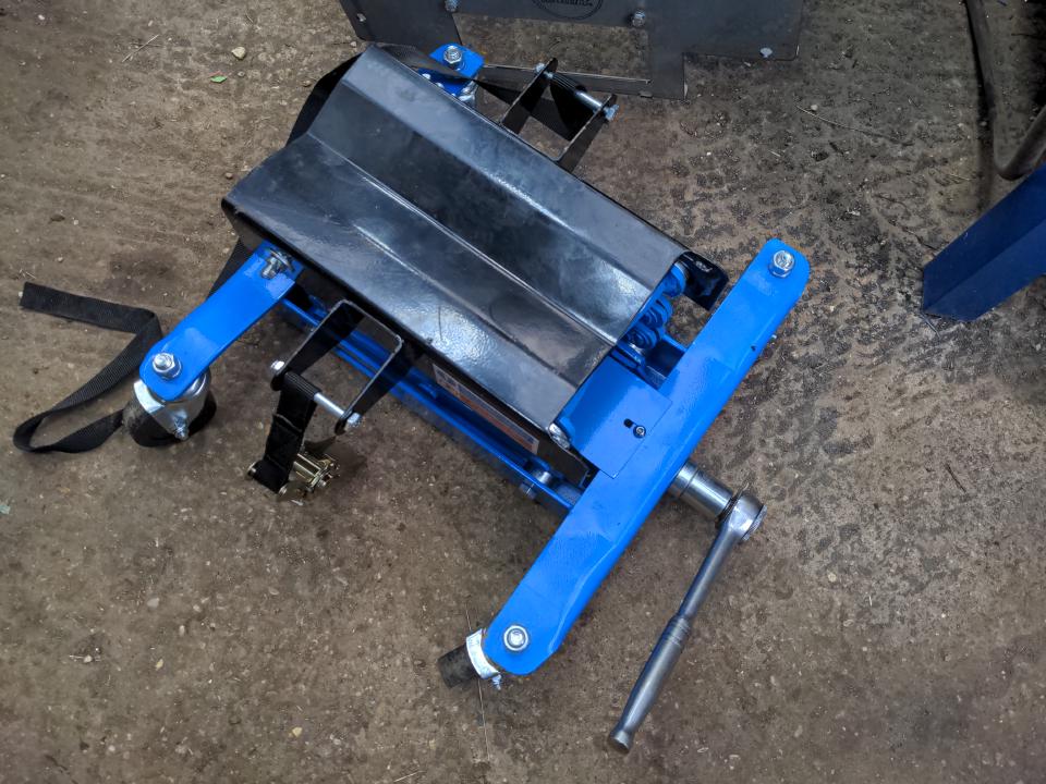
...and lifted the stunt engine up to the correct height with this jack designed for gearboxes (which means it has a perfectly linear upwards lift unlike a conventional jack)...
...and with everything in more-or-less the right place....
...bolt the steering box and relay into the subframe and see what fouls what.
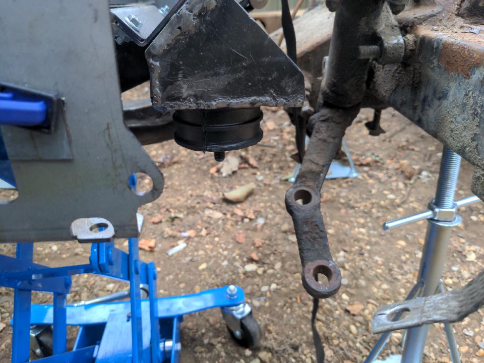
It turned out I can't use those GTO engine mounts, because they foul on the steering arms - even if they could bolt to mid-air there would be no clearance there.
Shame, because I liked them, and didn't really want to make my own, but needs must. I made an initial version of my mounts out of cardboard.
Which was fine, except there was no space to get a bolt into the engine block, so I came up with a second one...
...which I could fit to the stunt engine block using a bolt. Which meant I could turn that into steel, and to talk about turning it into steel we shall have a brief diversion about tools.
Tools! I like them! Tools help you make things! And yet I am prone as anyone to thinking that just one more tool is going to solve all my problems. What I actually needed to do instead of buying more tools was to use the ones I have.
Some of those tools are three 115mm angle grinders. They all perform exactly the same. I like having one with a cutting disc, one with a flappy wheel disc, and one with a grinding disc. It saves having to change discs, which I don't like doing because life is short.
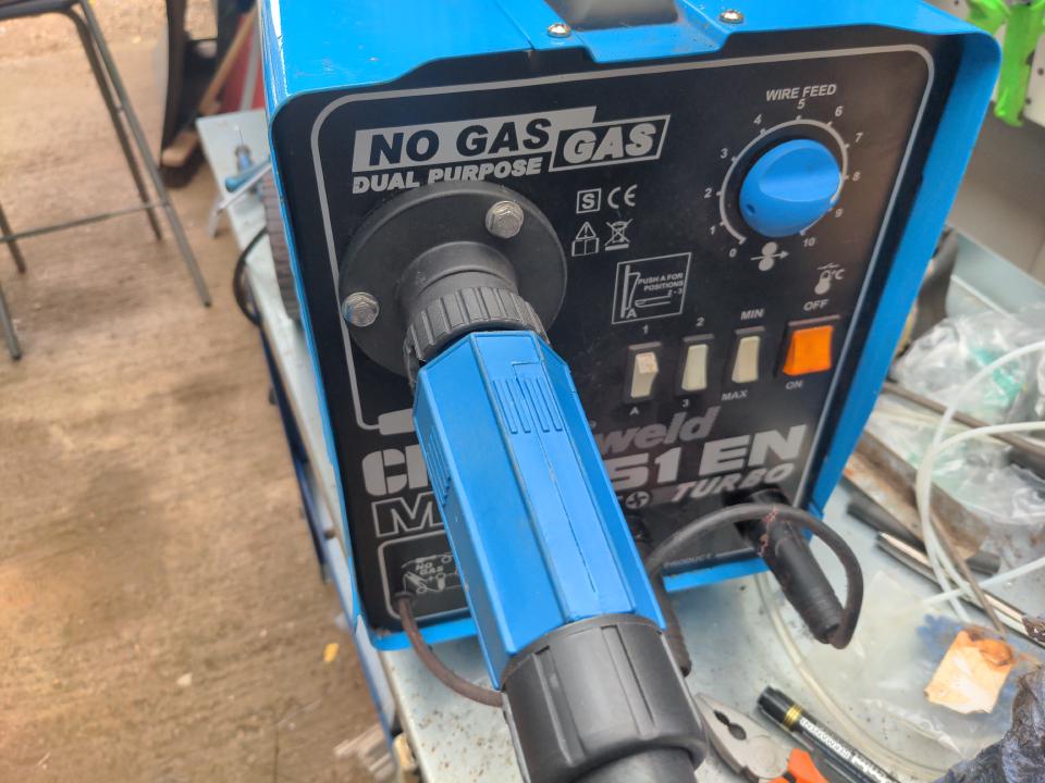
The other one is a cheap MIG welder. It's a Clarke 151EN which my brother gave me for free (thanks Alex), which he bought for about £200 in 2013 and didn't use much.
I've converted it to use a Euro torch, to make it easier to find consumables. I also ripped out the gas feed from the welder to use it solely with flux-core (gasless) wire. A lot of people don't like flux-core welding. I kinda like it; I get nearly the same results and I don't need to worry about running out of gas. It's easy to get flux core wire from Amazon; it's more effort to get a gas bottle refilled. And I want to prove a point, and only to myself: that tooling is not what is coming between me and getting actual stuff done.
It's a cheap welder so I might burn it out before I've finished the subframe. Or I'll end up converting it to gas! But for now this will do.
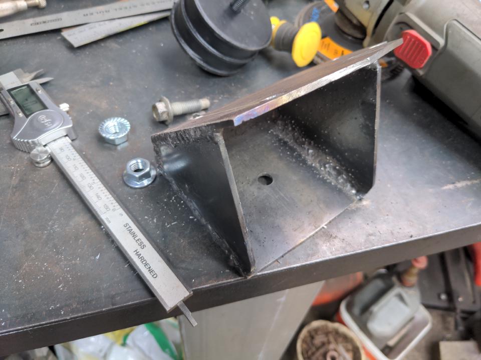
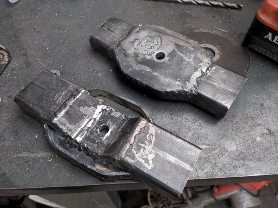
Anyway, with the cheap welder and a selection of angle grinders I turned my cardboard engine mount into 3mm steel...
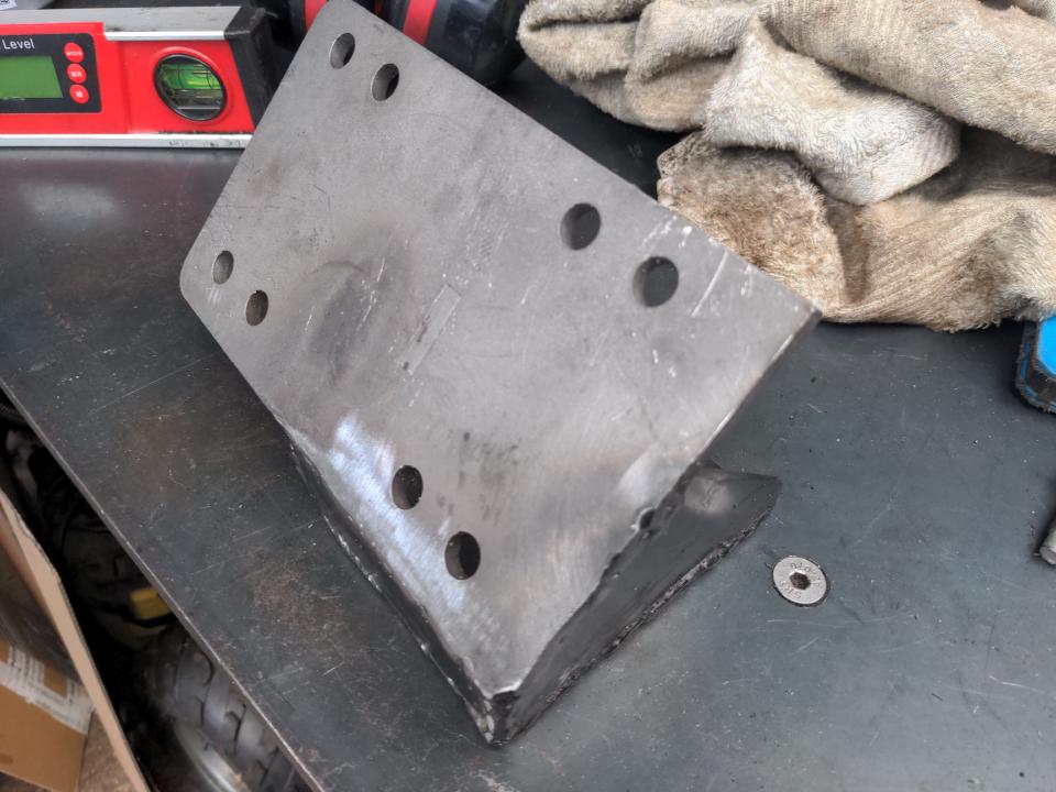
...and then remade it again with a 6mm main plate chopped off a generic LS engine mount, and 3mm steel for the rest...
...which almost solved the problems I had from the first round. (I'll still need to fettle it in the press a bit to get rid of some heat distortion from welding, and tidy up the welds; that can be done later.)
Those with some the mounting rubbers clear the steering arms with room to spare.
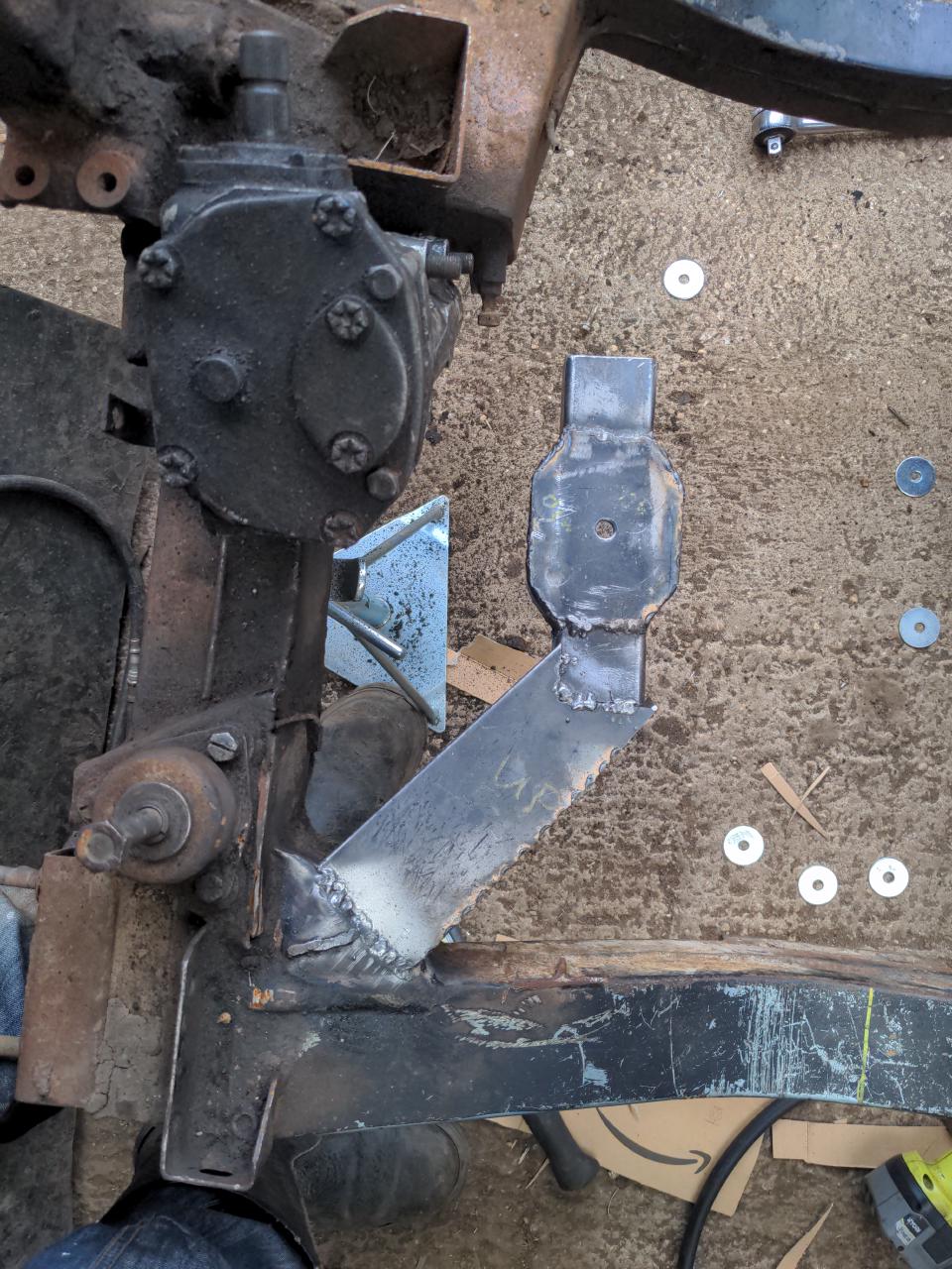
Nice! And I'll need that room to spare, because I need to fabricate some rails for these mounts to sit on. And that starts with these:
These took three revisions across three days to make. Someone who is good at this would have done it in a fraction of the time; I don't know what I'm doing, so it takes longer. That's part of the fun of this. I've never done an engine swap (if you don't count putting a slightly larger-displacement version of the same engine into a car), let alone an LS swap into something that never had an LS. I can chop up metal with an angle grinder and do an ugly job of sticking it together with a gasless MIG I got for free; those are my "skills". And this rules! If I only did what I know I'd still be soiling myself and crying for food. Just give it a go; what's the worst that can happen?
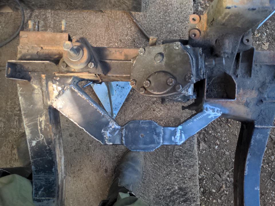
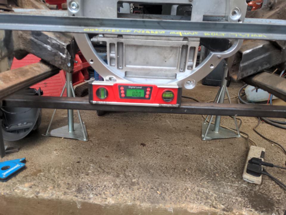
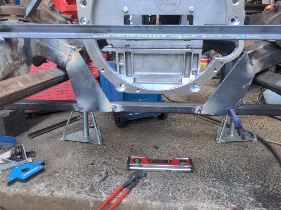
Anyway, the idea behind these sections of rail is that I can bolt them to the engine mount. Then I can get the subframe exactly level, and then get the stunt engine in exactly the right position relative to the subframe (rather than the crude approximation I did to check my steering clearances). This took three hours! And it required continued adjustment over the course of the day as the temperature changed and when I accidentally kicked the caravan stands. From there, you can fabricate outwards from the stub rails towards the front corners of the subframe. This is how a partly-completed rail looks:
And getting the engine in the right position gets a lot easier after the first quarter of these rails is in place! Here is how it extends backwards:
The box to which it extends rearwards (right in the pic above) is not strong enough for these purposes. It is a fairly-thin reinforcer between the suspension arm mounting points and the rear crossmember, which are strong enough for this job. I'll reinforce this box later.
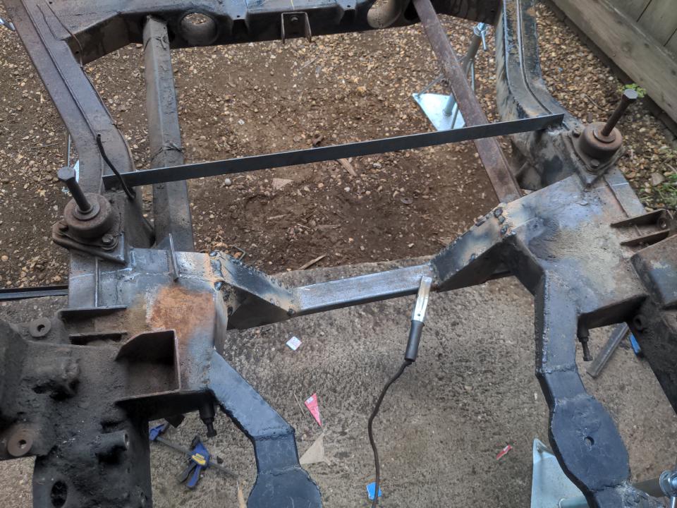
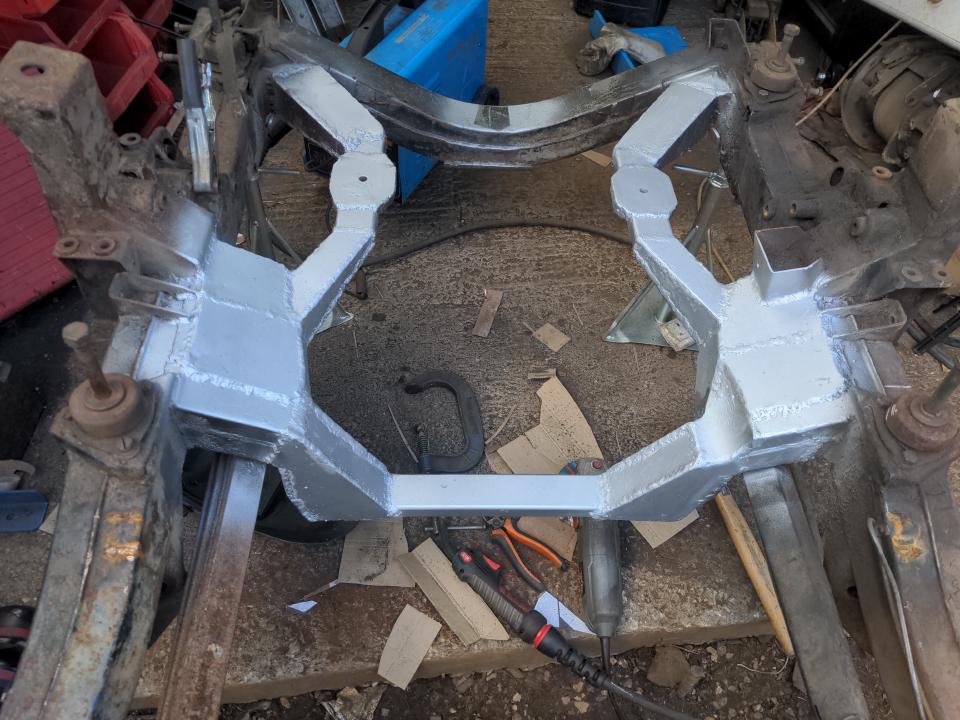
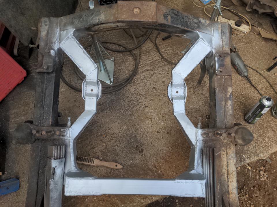
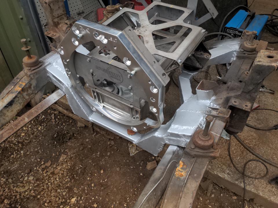
Anyway, spend nine days straight on doing all of those things and you get something that looks like this:
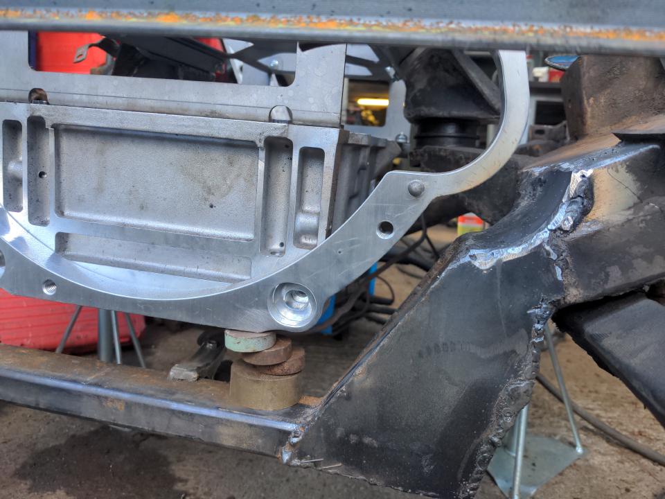
That's close enough to done for the moment; it holds the engine in the correct place and at the correct angles for us to move on for a while. Let's take a look at that alternator clearance again.
That nearly fits. Nearly fitting means "doesn't fit". But "nearly" also implies a couple of solutions that aren't top-mounting the alternator (which I don't want to do because this will merely move the clearance problem somewhere else rather than solve it). One of those would be to simply notch the new subframe rails a little. But I think it would be better to solve this by fitting a modern, more compact alternator. That's the obvious solution to me, because I want to replace my alternator anyway; it and all the other ancillaries on the engine came without no guarantee that they work.
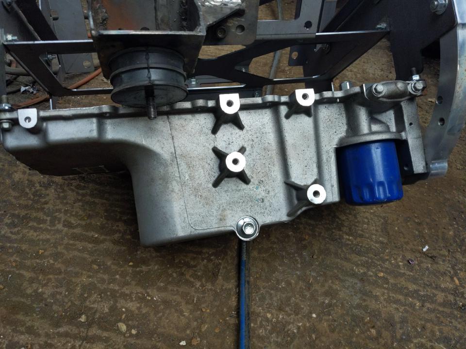
Let's talk about the sump for a second. It's abundantly clear to me that the original front-sump would never clear the steering gear. So I bought this Camaro rear-ish sump instead...
...which still won't clear the steering gear at the front! But it's a better starting point because it has the oil filter at the rear. That means it can be modified to fit. What I knew all along was that the rear of any LS sump won't clear the centre crossmember. There was a little clearance on a sump-less stunt engine - in fact, millimetres from clearing the centre crossmember with the rear sump. But modifying the sump at the rear is not a solution. The sump on the LS engines are structural; the bellhousing bolts to it. So there's a hard limit on how shallow you can make a sump at the rear, and I think the Camaro sump is as shallow as it can be in the areas that interfere with the crossmember.
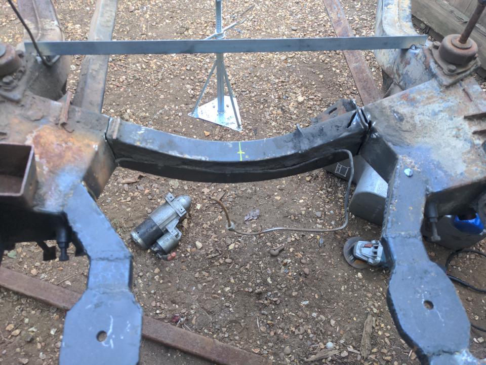
Instead, that means that we have to brace the chassis with some angle iron, cut the centre crossmember out...
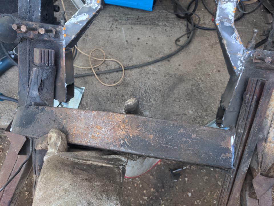
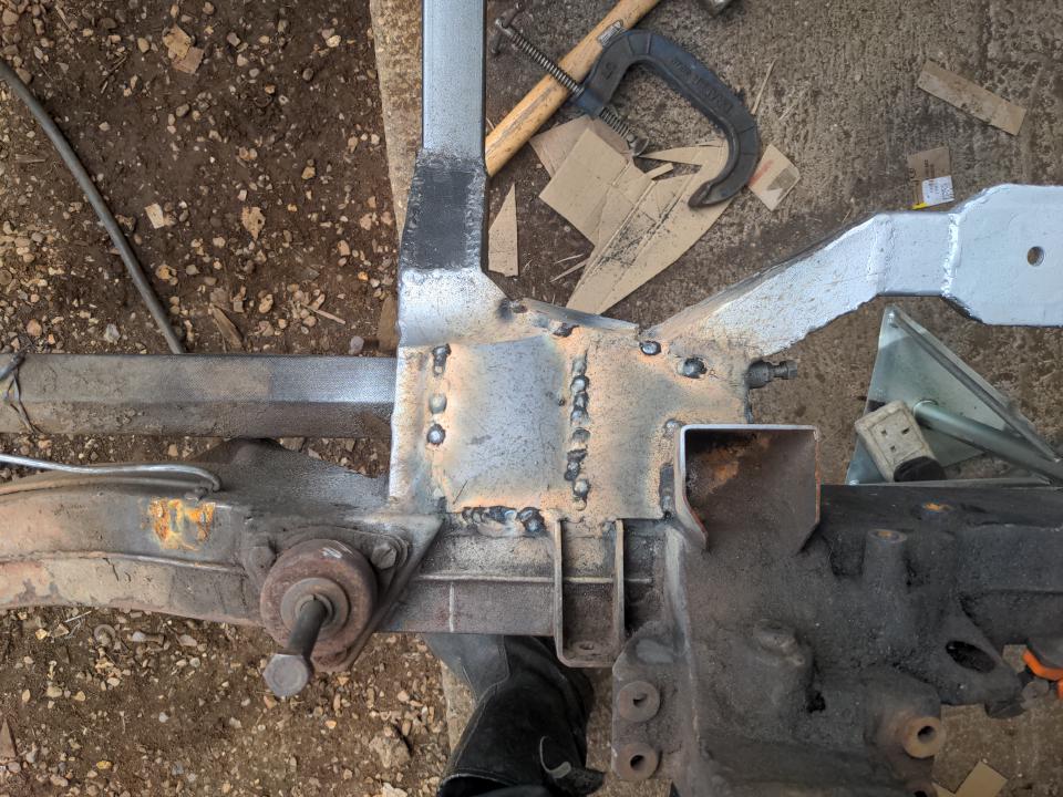
...and remake it, but about an inch or two lower. To do this, I took an oversized length piece of 25x50x3mm box section steel, and clamped that to some temporary angle iron pointing downwards from the outside of the chassis rail, spending as long as I needed to get it in exactly the right position.
From there, I could add some steel plate to hold it in place...
...and then add a whole load more steel and miles of flux core welding wire to make it into a centre crossmember, and by the way there goes another three days.
At which point I started to wonder how much of the weight savings from fitting an LS1 are being negated by the sheer volume of steel I'm putting into this!
After that, I knew that there was going to be some clearance problems around the starter motor. So I cut out some of the steel I just added, chopped a slice of 100mm steel pipe, and shoved that in the hole I made (it's just right of the rear of the engine below).
As promised earlier, I reinforced the box between the suspension arm mounts and the stub of the old rear crossmember by adding even more 3mm steel.
And with all that done, I could spend a day and a half going around fixing up my bad welds, cleaning up a little,...and add a little zinc-rich primer as a temporary to stop everything from rusting faster than a British car leaving the factory. While Chip Foose is not going to start hammering my inbox trying to hire me for my beautiful fabrication skills, it looks pretty OK for someone who has absolutely no clue what he is doing.
So that's where I am now: an LS engine (or stunt version thereof), sitting in a Rover P5 subframe, with most of the things clearing the things they need to clear. Some things need fettling, and some things might still need to be welded to it; this is not its final form. But this is done enough that I can call it done for now.
And that, is the easy part out of the way. :) See you next time.
Part numbers from this post:
- Stunt engine: Speedway Motors SoloSwap 12640748
- Transmission jack: Draper 09021
- Welder: Clarke 151EN
- Sump: General Motors 12640748
- Die grinder: Sealey SA671
- Zinc primer: U-POL WELD/AL
- Cardboard: Amazon single-skin envelopes (from my deliveries), Felix cat food boxes
- Steel supplied by Thomas B. Bonnett
