I modified my welder, didn't die
This is my MIG welder.
I wrote about it briefly when talking about the time I lost the plot.
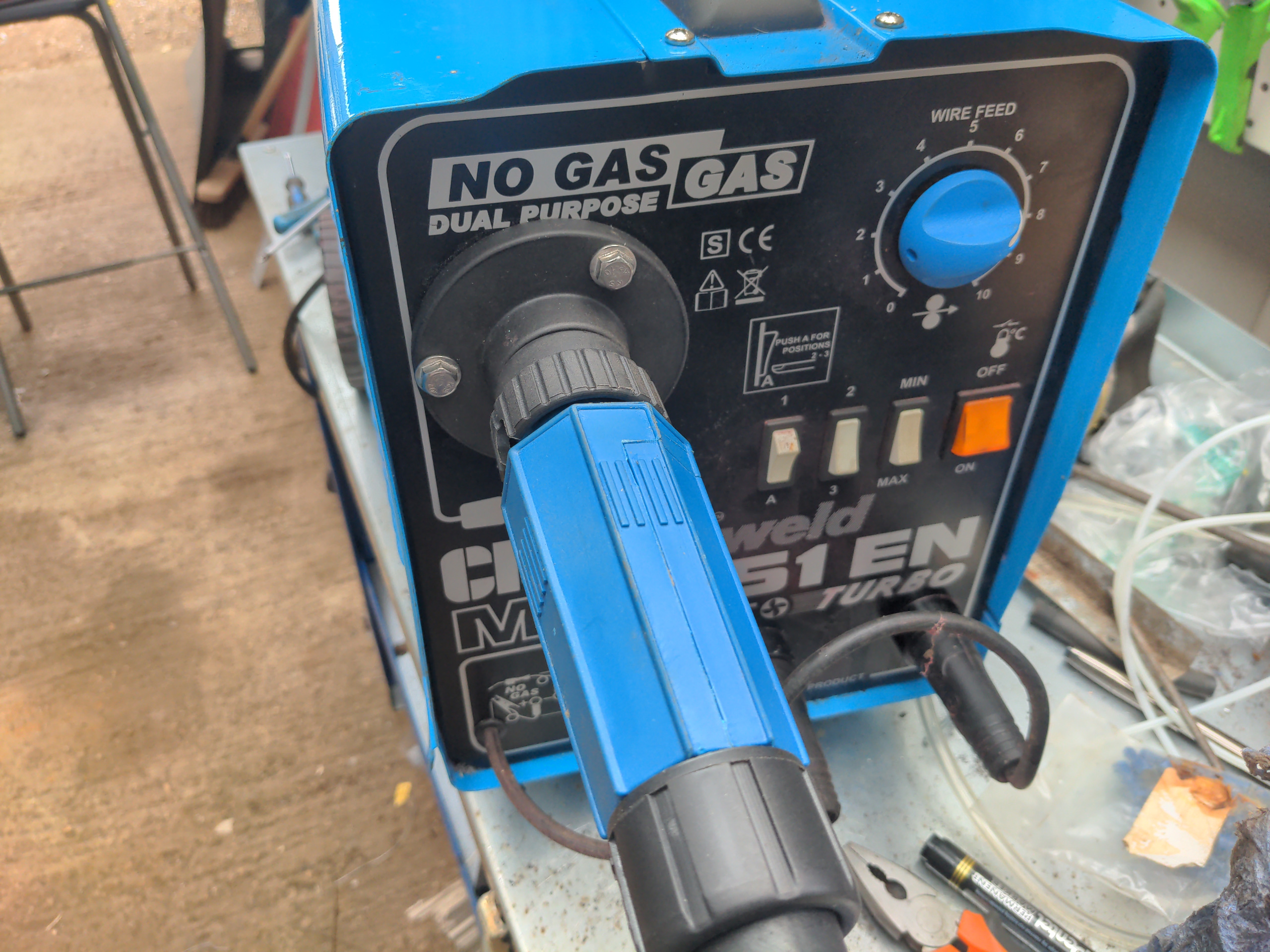
It's a Clarke 151 EN, which was a cheap welder when it was new (about £200 in 2013). It is even cheaper for me, because I got it for free from my brother last year. He bought it and never used it much, and decided it needed a better home, so he gave it to me. As for you, you could probably pick up a similar machine for less than a hundred quid these days if you look around. If you find one it'll probably be in perfect condition, because people who use welders to the death tend to buy expensive professional machines, and people who buy hobby welders like this tend to use them very occasionally.
If you hadn't noticed from the photo above (and also if you had), I modified mine to use a Euro torch. I did this out of frustration with the availability and quality of consumables for the Clarke torch. Euro torches all use the same generic consumables, so they are easy to find, and it is easy to find high-quality ones by buying a known brand rather than CSQQXV or whatever on Amazon.
What I didn't do was fit a gas solenoid. Flux core (gasless) welding was fine for what I was doing, and it didn't take me long to get the hang of it, so I pulled out the remains of the gas feed and called it finished, and used it for about nine months with no problems.
And it still hasn't given me any problems! But one of the characteristics of flux core wire is that it loves heat. You need to run about twice the power for any given thickness of material as you would when welding with gas-shielded solid-core wire (which I like to call gasful welding, because that is fewer words and I find it funny). That was fine for what I was doing.
But the next subproject of my Rover P5 will require welding things onto a very fancy axle housing.
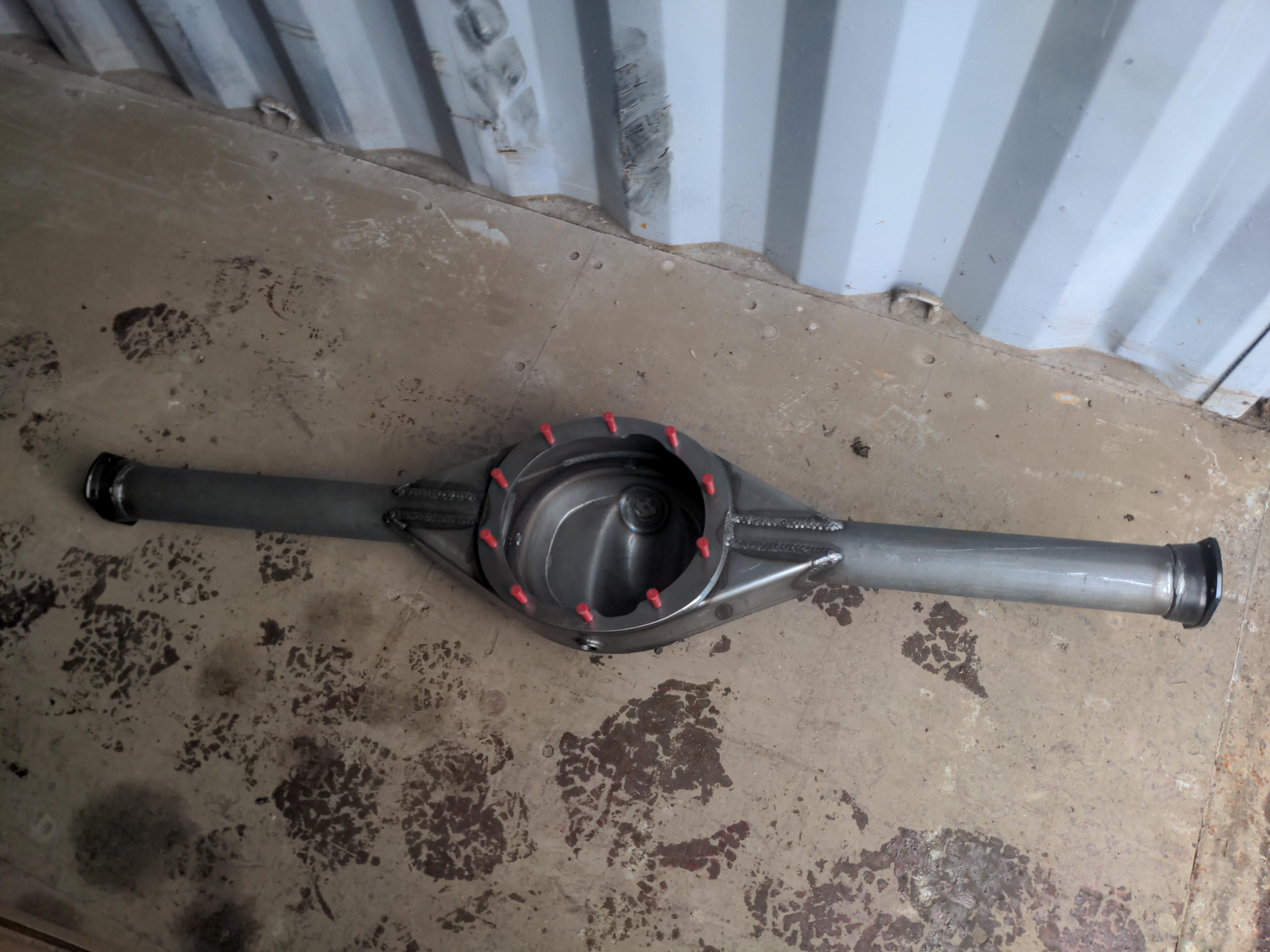
A millimetre or two of heat distortion on the axle housing would ruin the housing, probably permanently, and I (literally) can't afford that to happen. Thus I need to do the same thing with less heat, and so I needed to convert this welder back to gasful operation.
And even more context here, because like cats, you can never have too many contexts.
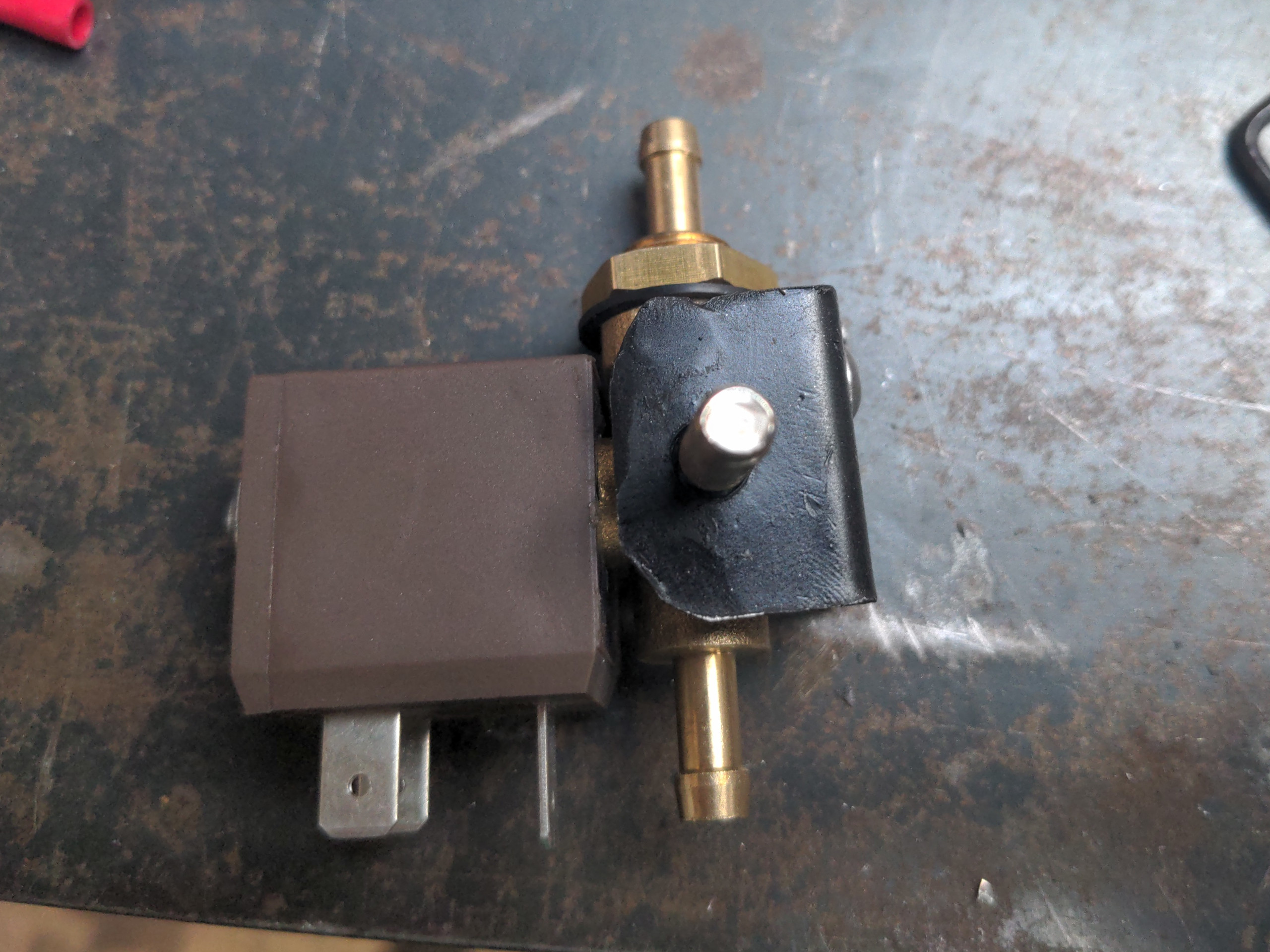
In most cheap MIG welders, shield gas flow to the nozzle is controlled by a valve in the torch, which looks like this:
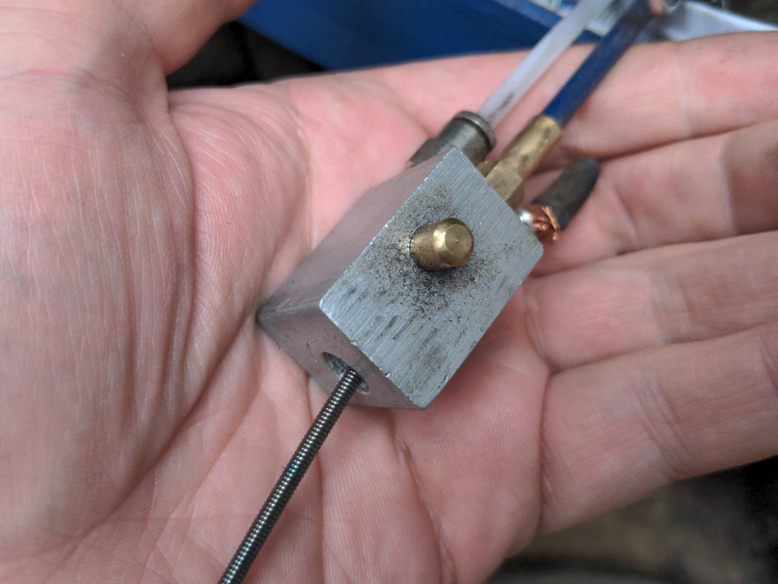
The gas ordinarily fills the pipework all the way from the bottle up to this valve. When you press the trigger, the trigger directly (mechanically) opens a valve which lets the gas through. Simple.
On a Euro torch, there is no such mechanism. Instead, welding machines with Euro torches will have a solenoid in the welding machine itself controlled electrically; when you press the trigger, the solenoid is turned on and gas flows into the torch. So to have a Euro torch, you need to install a solenoid somewhere. Which is what I did!
I rather wish I had written a post like this about fitting the Euro torch itself back in June of 2024. I didn't, because I was in a rush, because I needed a working welder on a short timeline. Instead, I watched a YouTube video.
That went into lots of detail about the fitting of the torch itself, and if you are doing the conversion yourself you should watch it. But it was, to my mind, rather light on the details of installing and wiring the solenoid. That might scare some people off, because that means going into the "spicy" side of the welder with the voltages that can kill you instantly. It scared me until I actually did it.
That's why I'm documenting it here: to show you exactly what to do, to demonstrate that it is not scary, and also because I like the sound of my own text.
Here's the things you'll need:
- A gas solenoid
- Some angle iron or other random bits steel you have kicking around for making a tiny bracket, and (probably) two M4 screws
- Three 6.3mm female spade connectors
- Two 6.3mm piggyback spade connectors
- One M4 ring connector
- Cable ties
- Wire, in brown, blue, and yellow/green colours
- 6mm (ID) flexible plastic tubing
- At least two and ideally four hose clips of the same outside diameter as your plastic tubing
- A grommet
- (Probably) A 3/8 BSP male to 6mm hose tail fitting
I'll tell you more details about the "why" of these things as we go.
First, you'll want a gas solenoid, obviously. I bought mine from Weldequip. I could have got one cheaper by getting something from an Amazon or eBay non-brand, but I would rather buy electrical things of non-trivial complexity that could kill you if they go wrong from a company with a reputation to maintain. I use their picture of their solenoid below, because I didn't think to take one of mine.
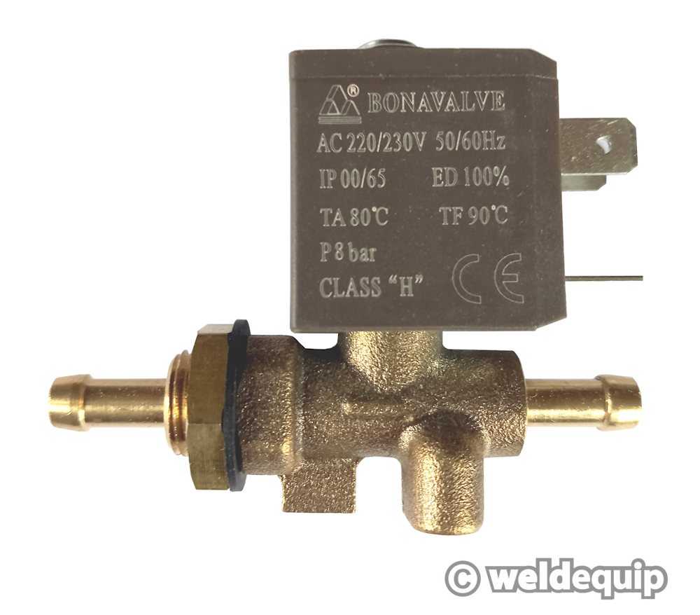
For the Clarke 151, you will want an AC 220/230V 50/60hz solenoid. This is probably the case for other hobby welders, but you'd best check this yourself.
And on the subject of voltages, we're entering the spicy side of the welder here, so please observe the following safety precautions:
- Don't get killed
- Yep
Of course you know to open the welder with the mains power turned OFF at the plug to the welder, not just turned off on the orange switch on the front of the welder. Before touching anything inside the welder, I prefer to turn off the welder at the plug, then unplug the welder entirely. You might think that one of these steps is redundant; electrically speaking, you would of course be correct. But for me, unplugging the machine is an active step that is difficult to forget; this also means I have to forget two things for there to be any voltage at the machine, rather than one.
Anyway, unless your solenoid comes with a bracket, you'll need to make one.
I made mine with a little offcut of thin angle iron with a captive M6 bolt welded onto it. The bracket is attached to the solenoid with two M4 screws (using holes that existed in the solenoid for this purpose). There is already a hole in the divider for attaching something in roughly the right place for a solenoid, but it's too small for an M6, so I bored it out with a 6mm drill bit.
Whatever you do for this bracket, remember to obey the direction of gas flow! This is indicated with an arrow on the body of the solenoid. Gas solenoids only control gas flow in one direction, and they won't work if you reverse the flow. The arrow should of course point towards the front of your machine, because that is where the gas will be travelling.
Wire up the earth
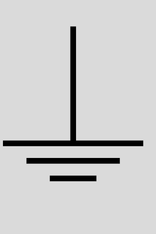
Our first electrical connection will be the earth (also known as ground). Of the three prongs on your solenoid, you can tell the earth terminal in one of two ways. First, the earth prong will be marked with the earth symbol, which is this:
If no prong has this marking, your solenoid is dangerous shit that needs to be thrown in the bin; get one from Weldequip instead. But also, of the three prongs, one of them will be oriented in a different direction, and that is usually the one that will be earth. You can see that in the photo of the solenoid above; the power prongs are angled horizontally, and the earth is vertical.
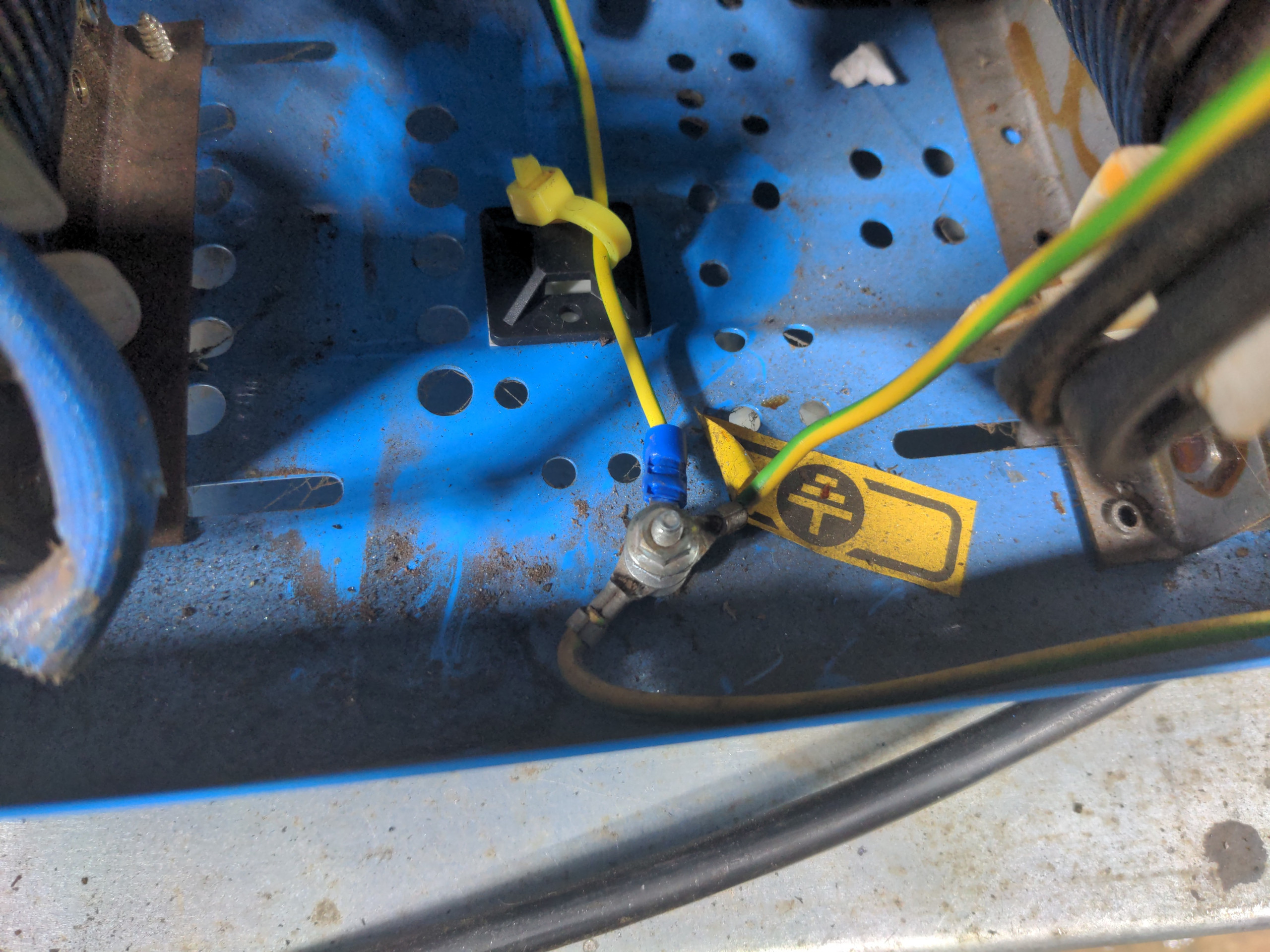
You will want a yellow-green wire for this. It will need a 6.3mm spade terminal on one end and an M4 ring terminal on the other. Attach the spade terminal to your solenoid, then run the wire along the body of the welder (not the shortest possible route) down to your earth point on the bottom plate of the welder, and once you know the wire's length, cut it and crimp on the M4 ring terminal, and bolt it to the earth point. The earth point looks like this:
I like using the correct-coloured wires, and you should too. Of course, electrically it makes no difference. And of course you, right now, are smart enough to look at the thing you just wired up and know what does what. But you in future might look at the wrong-coloured wires and misread it. The person you sell or give your welder to in the future might do the same. Use the correct colours to be nice to future-you and others. :)
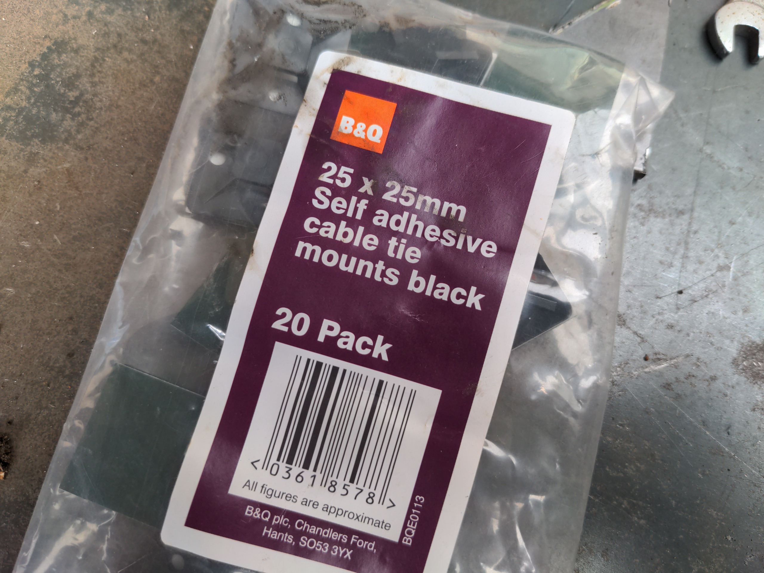
When attaching wires (and other things) to the body of the welder, I used these self-adhesive cable tie mounts, because I had a bunch of them left over from wiring the workshop. They're like £2 a pack from B&Q.
Wire up the power
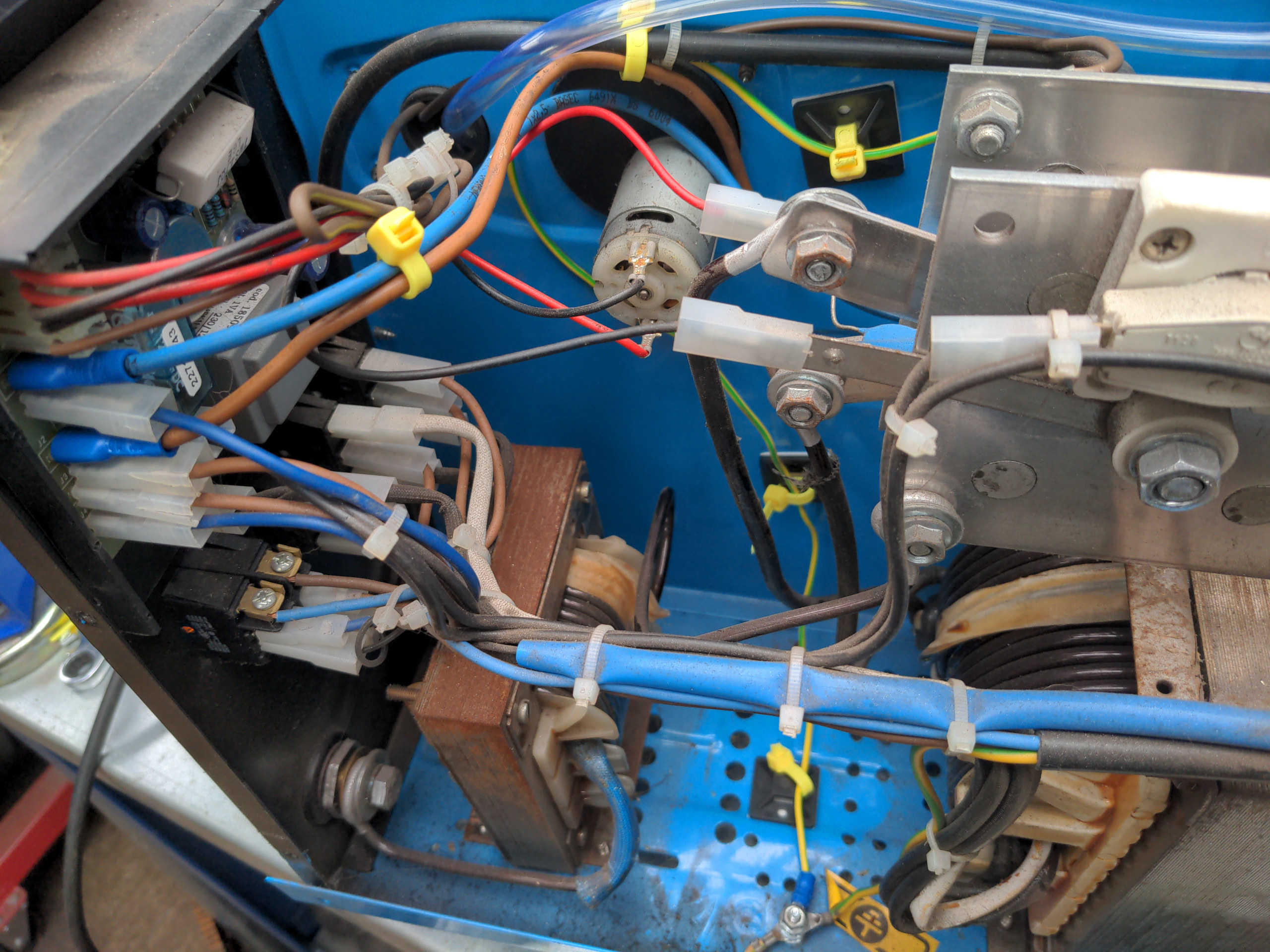
The next two wires will piggyback off jumpers J1 and J2 on the main board on the front of the welder. I've indicated them below.
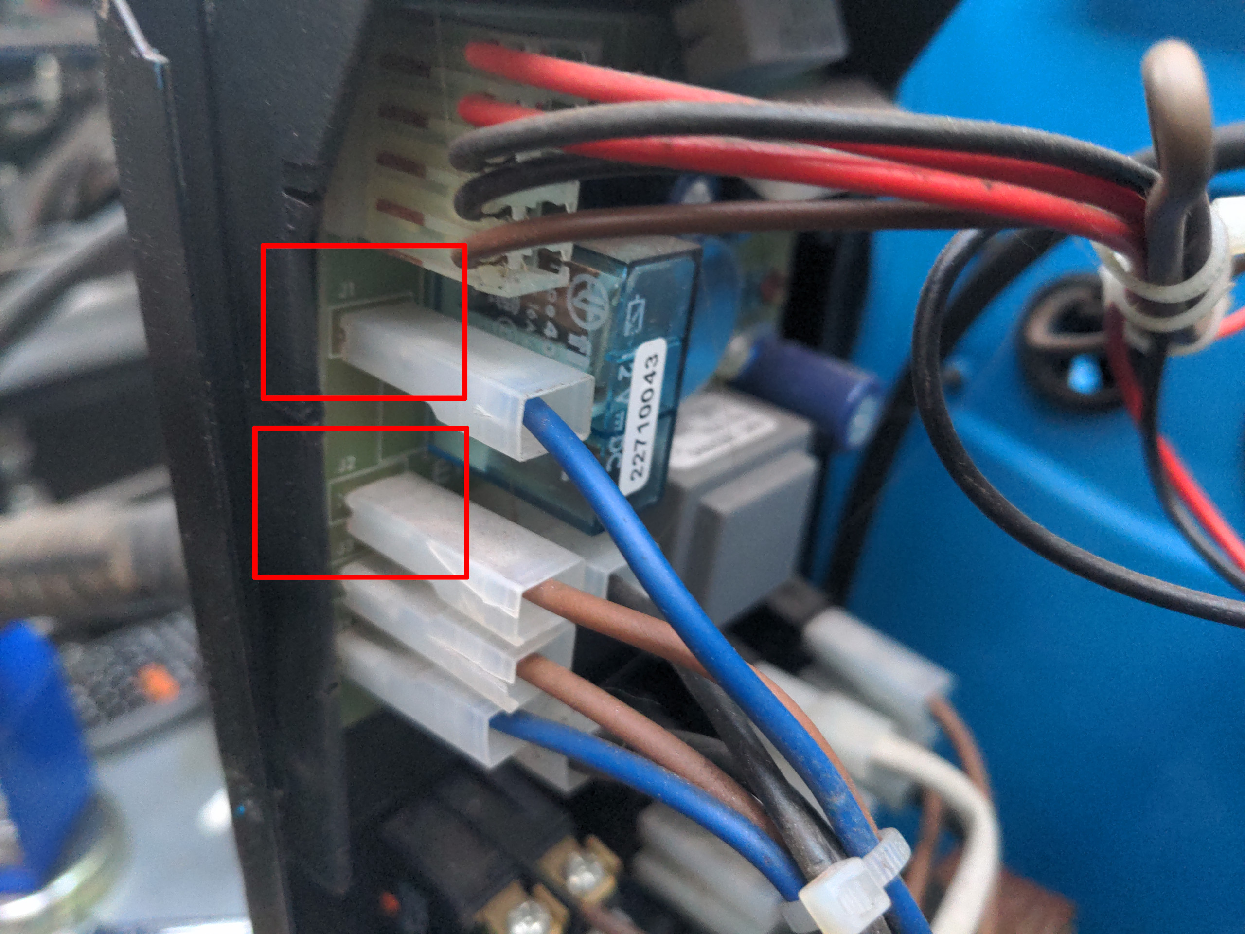
Obviously each one already has a connector going to it. So what you will need is a piggyback connector.
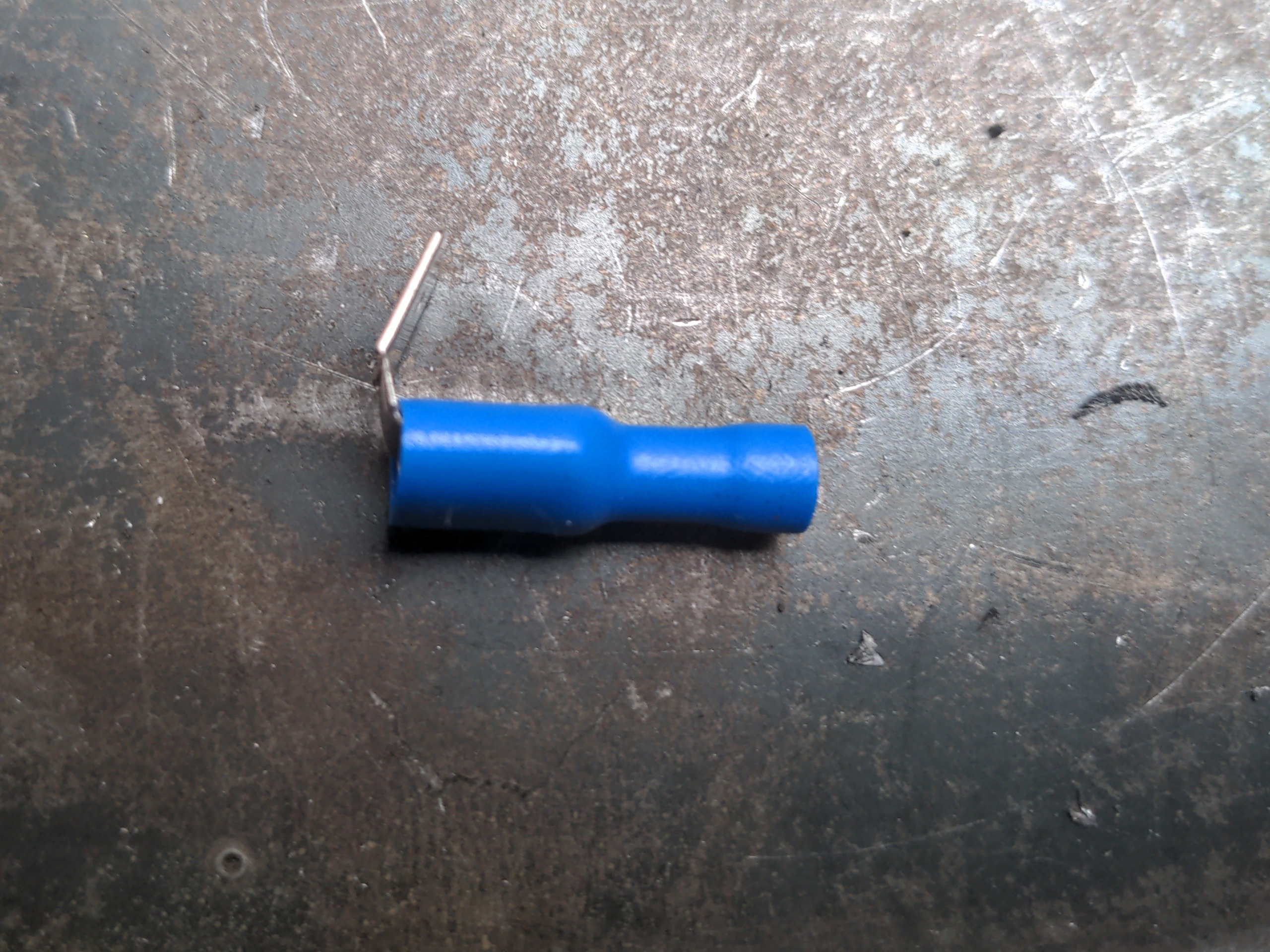
This is a connector which slides over a male spade terminal, and provides another male spade terminal on the other end. That'll allow you to connect two spade connectors to a single male spade terminal. Disconnect the existing connector from the J1 terminal from the board. Crimp a piggyback connector onto a wire of the correct colour (blue), push the terminal onto the connector on the board, and then push the original connector on to the piggyback terminal. Repeat this but with J2 and brown wire.
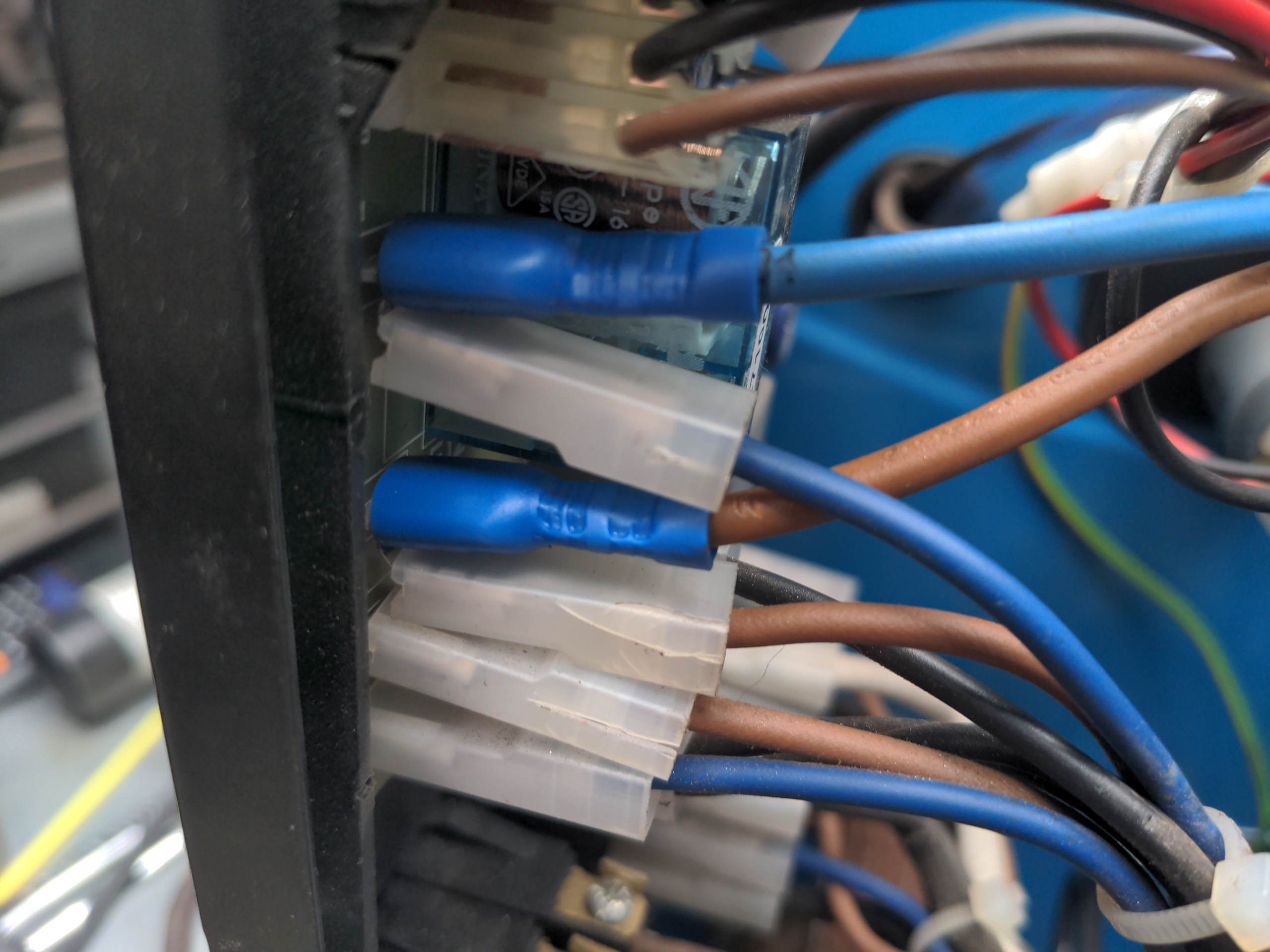
These will go back to the remaining two terminals on your solenoid. It should not matter which wire goes to which of the remaining terminals; solenoids should work the same regardless of polarity. It's up to you how you route them but it's best to follow the path of existing wiring as much as you can.
Test the solenoid
At this point your solenoid is electrically connected. It would probably be wise to test it at this point. Plug in your machine and turn it on, pull the trigger of your torch. You should be able to hear the solenoid clicking when you pull it, and clicking again when you release it.
Watch the front board around the area of your piggyback connectors; if you see sparks then unplug your machine, re-seat the connectors, and try again.
Turn off and unplug your machine after testing.
Hook up the gas feed
Now for the relatively safe bit.
I mentioned flexible plastic tubing with a 6mm internal diameter. I used PVC tubing for mine. Silicone tubing is rather more heat-resistant than PVC, but PVC is somewhat stiffer for any given wall thickness, so it better resists folding when going around tight bends. I chose PVC because of this; I don't think heat will be a problem.
This should be 6mm ID, because that is the standard diameter for the gas port on a Euro torch socket. It is also likely the same as the inlet and outlet of your solenoid. If you are using disposable gas bottles (as I am to prove the concept; I'll move on to the big refillable bottles later) then you likely have some tiny push-in fitting on your regulator. Depending on the quality of your regulator, you might be able to unscrew the outlet port of the regulator and screw in one of these...
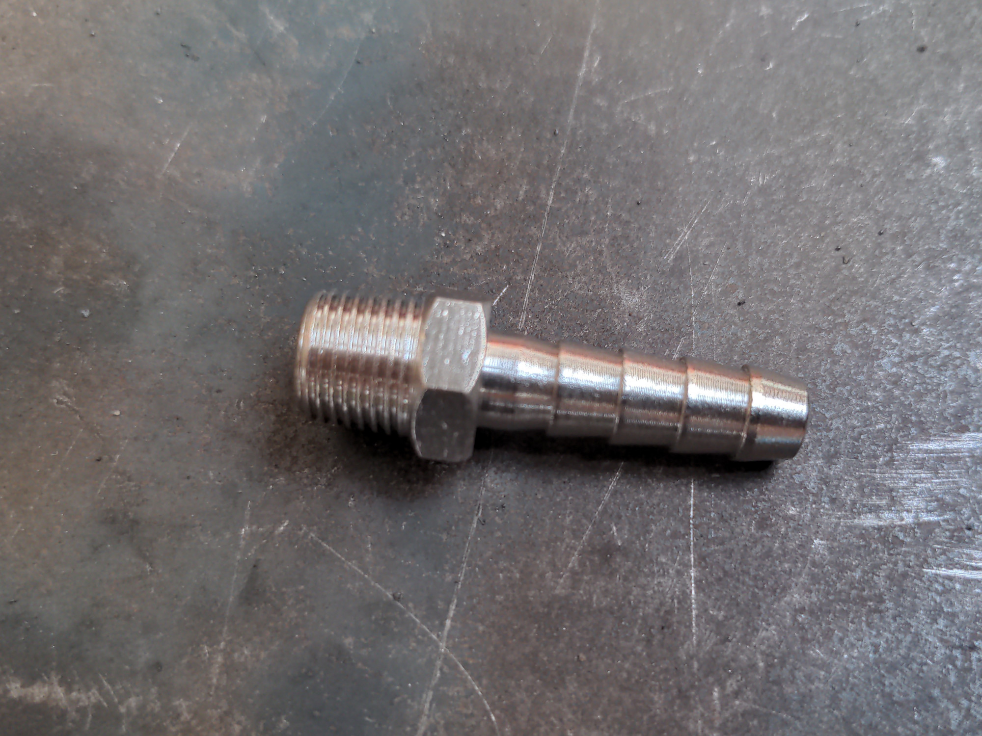
...which is a 1/8 BSP to 6mm hose tail. If your regulator has no provision for that, you'll have to get some step-up adapter in the middle of your hose.
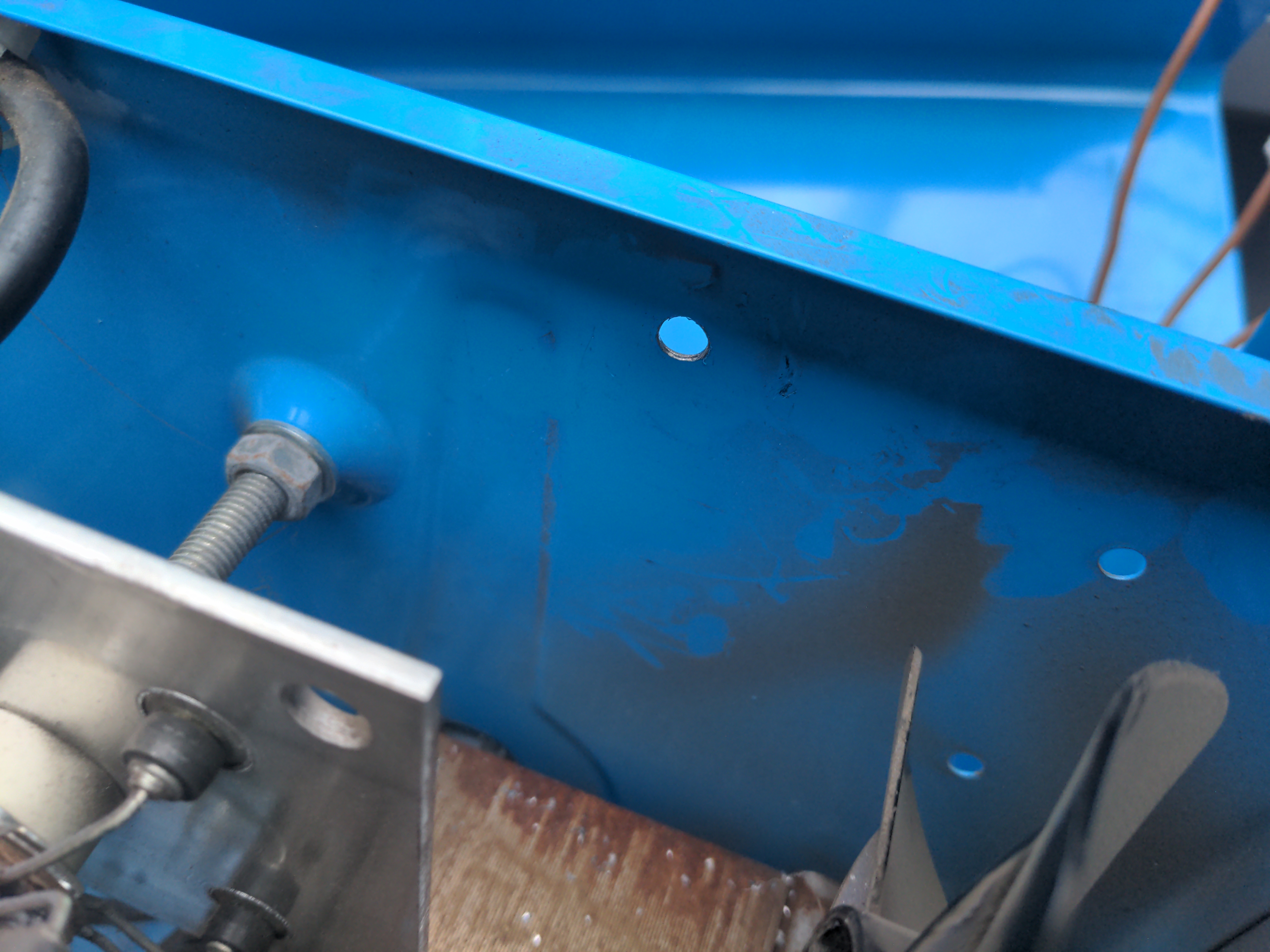
From your solenoid, you'll want to run your hose out the back of the welding machine so that it can meet your gas bottle. I drilled a hole just to the left of the one that exists (which could not be bored out larger because it's right next to the middle dividing plate). I put a grommet in it when routing the hose, so it doesn't cut the hose. I didn't think deburring the hole would be sufficient guarantee against that.
The downside of locating it here is that this is where the gas bottle wants to sit, so the bottle has to be strapped on at a weird angle. I didn't hear the bottle complaining about this, and anyway it's under my workbench so I never see it.
Exiting here is really tight on the cooling fan...
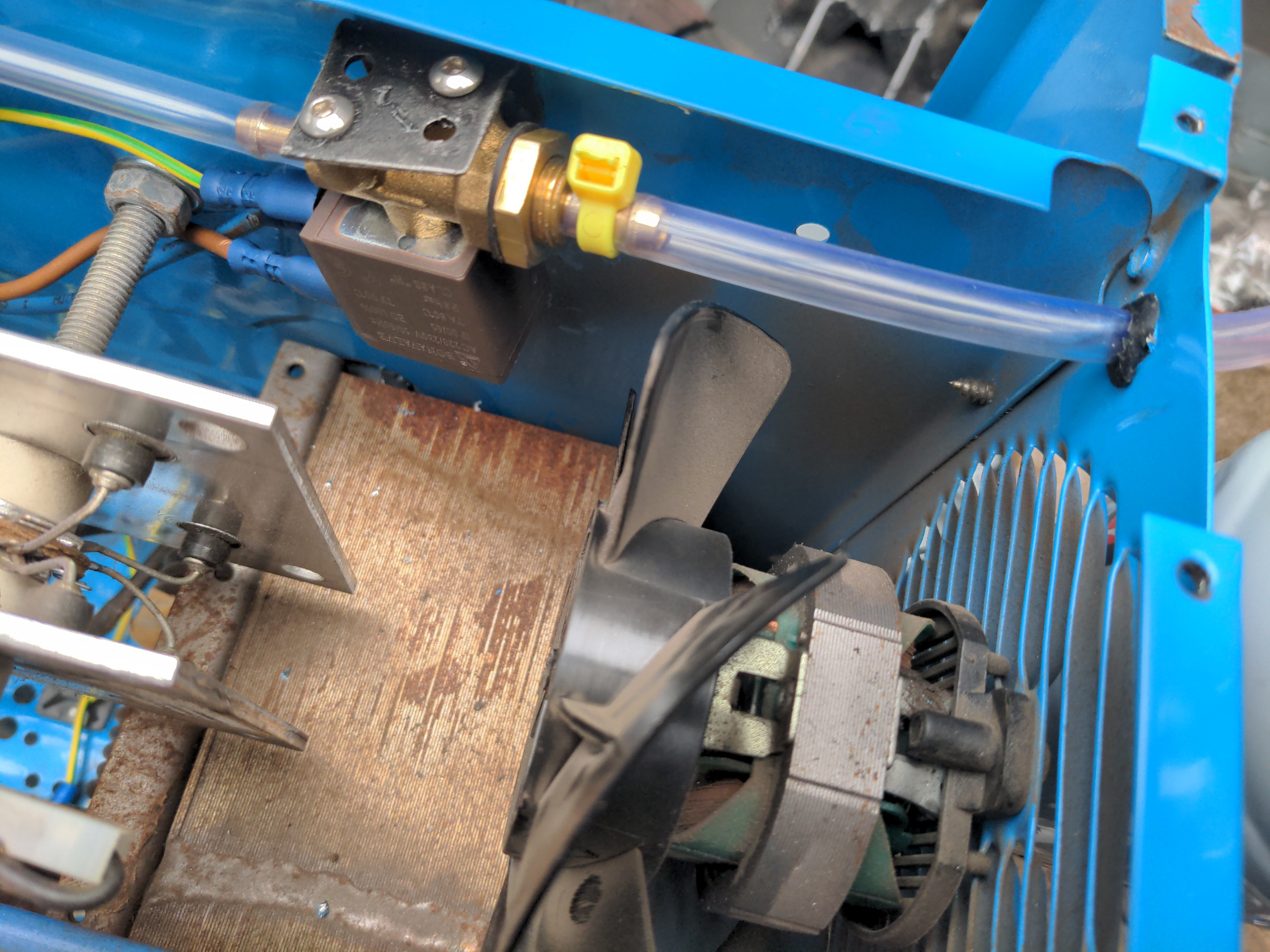
...but "it's tight" is another way to spell "it misses"; the only way this could foul is if some of the external part of the hose was pushed back into the machine, and the grommet should stop that from happening.
In future, when I move to the bigger refillable bottles, I might route the air hose into the cold side of the welder and out of the body of the welder as far over to the edge of the machine as I can. We'll see.
You'll see that I used cable ties for attaching the gas hose to the solenoid, which is what I used anywhere else the hose needed attaching to something else. This turned out to be inadequate for the section from the gas bottle to the solenoid. It leaked. After a failed trip to my local motor factor to obtain some proper clips for this, my brother came up with the idea of stripping some of the single-core wire I used for the wiring and twisting it around the hose. It's an expedient field repair (bodge) he learned on his intercontinental road trips.

It's crude, but it works! I only needed to do this for the section from the bottle to the solenoid. It's not necessary for the rest. That's because any time there is gas in the rest of the pipework, it will be flowing to your torch, and that is the path of least resistance vs leaking. And that's why I said in the list of ingredients that you'll "at least two" proper cable clips, because you only actually need two.
I'll soon replace all of this with proper 8mm hose clips for consistency, but this works fine for now.
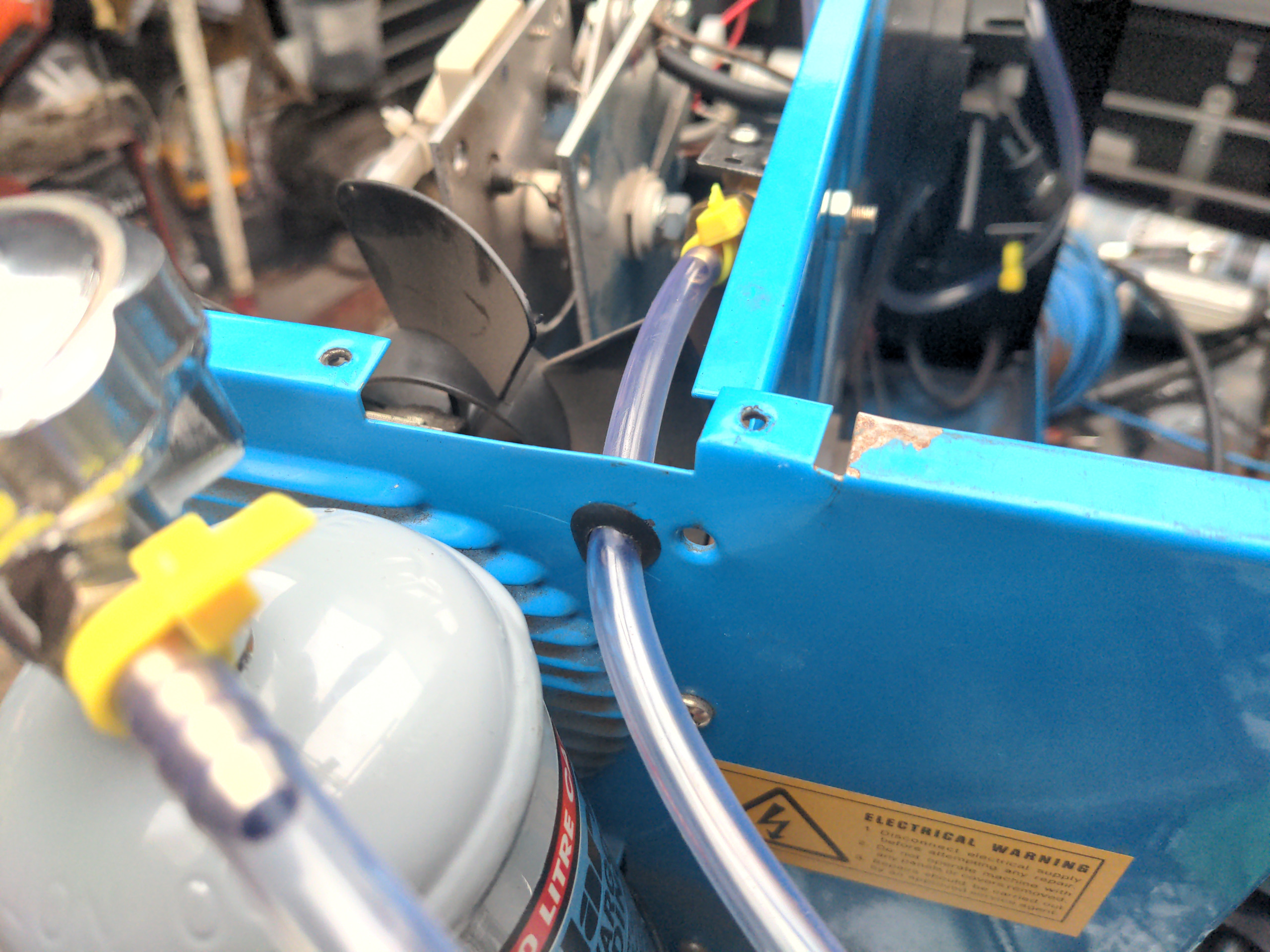
Anyway, the final task is to run the hose from the output of the solenoid into the gas port of your Euro torch socket. You can do this how you like. You could make a hole in the spicy-side divider immediately after the solenoid and make most of its route on the cold side. I choose to route as much as I could along the top of the spicy side of the welder, and exit through the bottom of the wire feed box. I hope you can see what I mean by looking at the top of this photo of the spicy side....
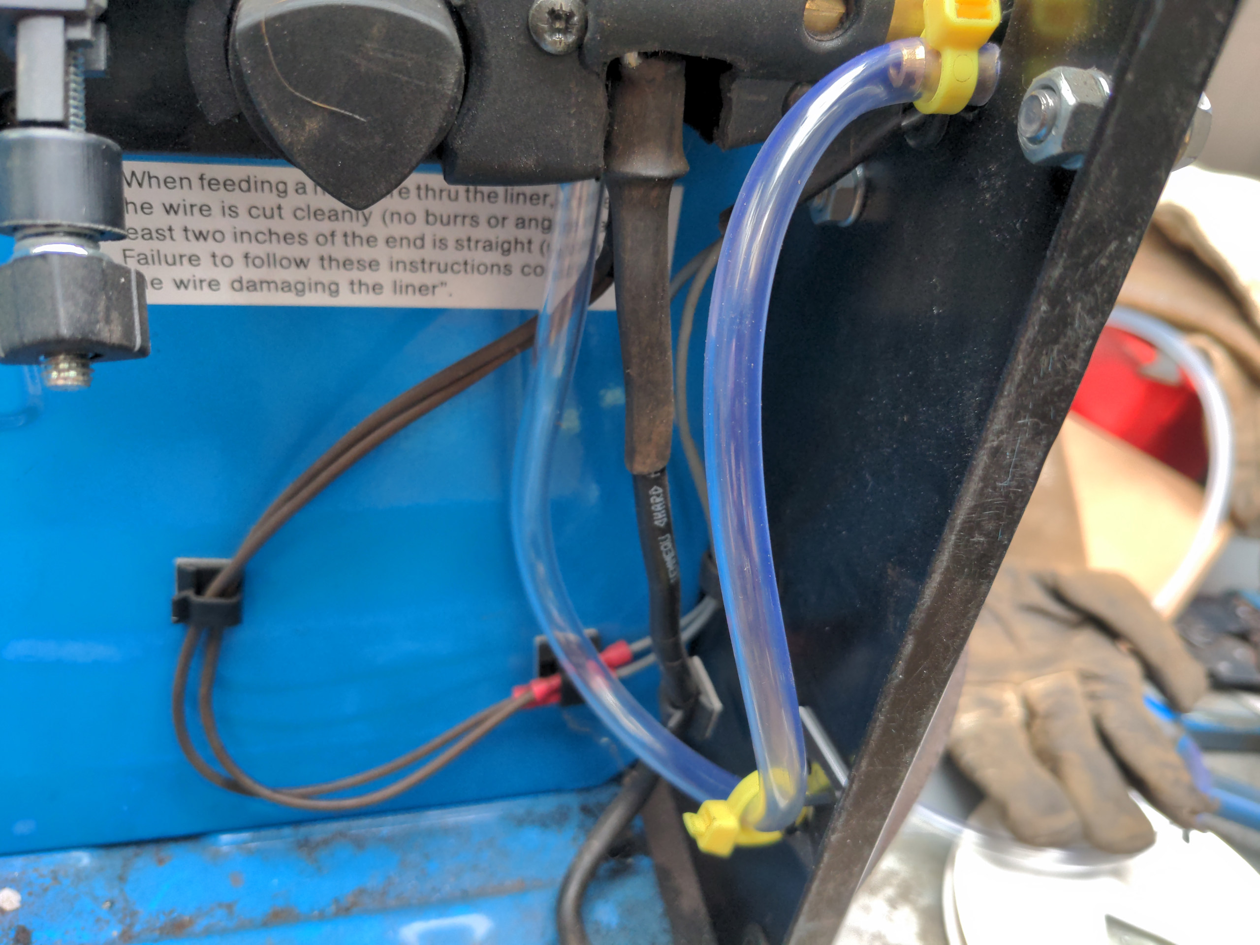
...and then at this one near the gas port on the Euro socket.
That's it!
Anyway
So like, I had no clue what I was doing with any of this and somehow made it work. The reason I did this, as said, is because I need to weld stuff to a fancy new axle housing. When I bought my axle housing, I also bought a short section of exactly the same tubing.
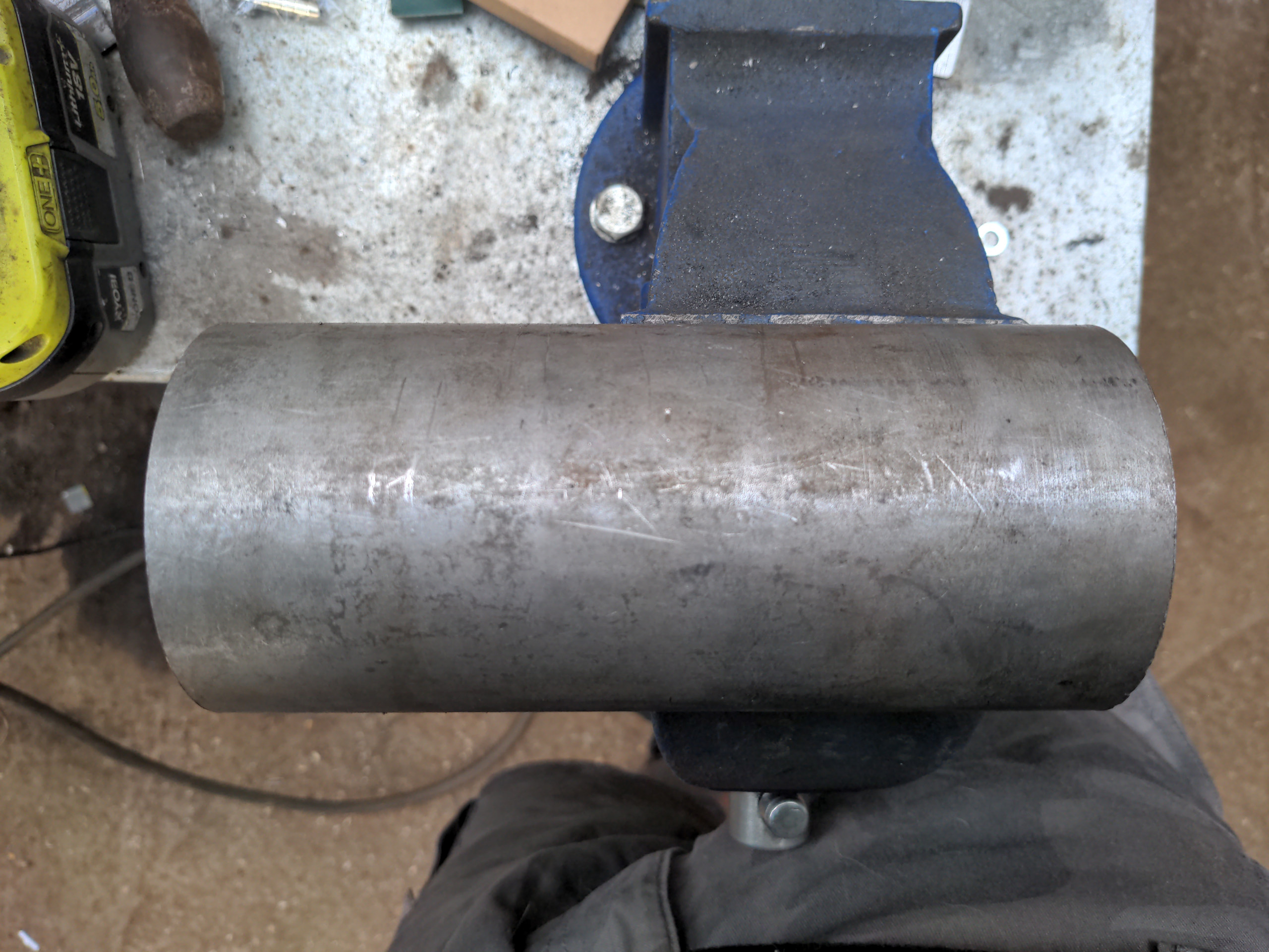
I got this section for practice to work out the correct settings on my welder before doing the real thing, and that's why I spent much of a Saturday turning it into the Frankentube of Wat.
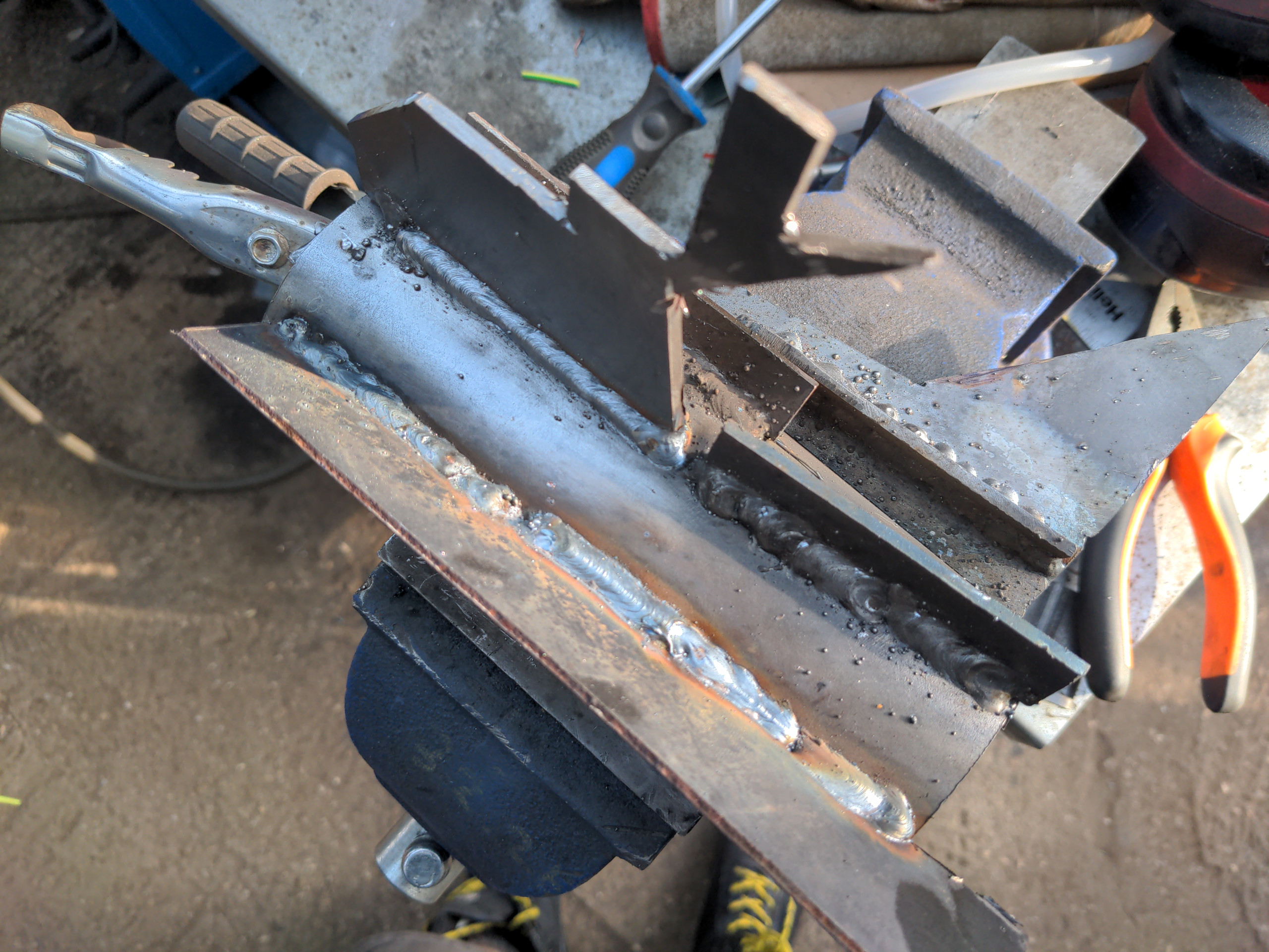
By the end of it, I was pretty sure I know what to do, and it didn't take me long to get almost-neat-looking welds with the gasful setup.
And that, of course, is the next chapter of the P5 saga entirely given away, which means you won't need to read that post! Two articles for the price of one! See you next time.