Remaking Rover P5 rear leaf spring perches
These are Rover P5 leaf spring perches, which aren't actually from my Rover P5.
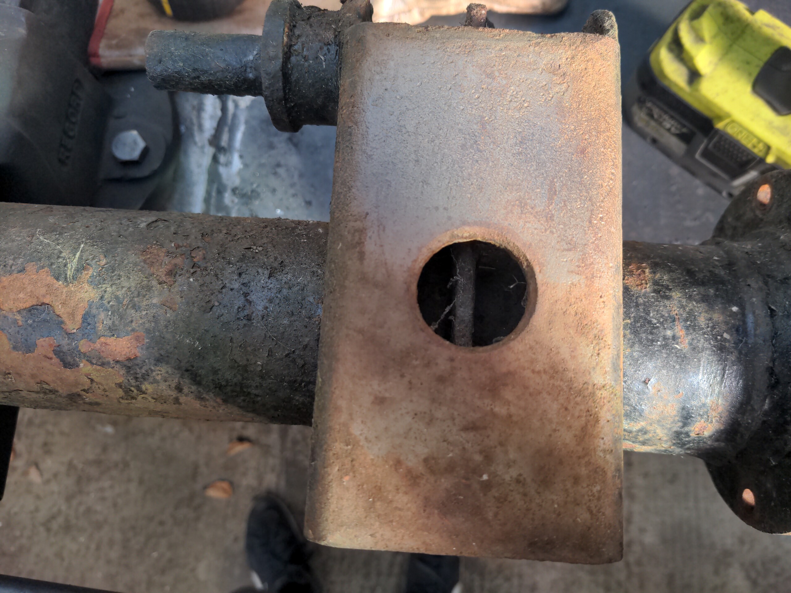
These weld to the axle and have the leaf spring clamped to the bottom of them. I needed some of these because I will be running standard rear suspension on my LS-engined P5, but I will be using a completely different axle housing, about which there will be more very soon. But what I didn't want to do, was chop up my old axle for these parts.
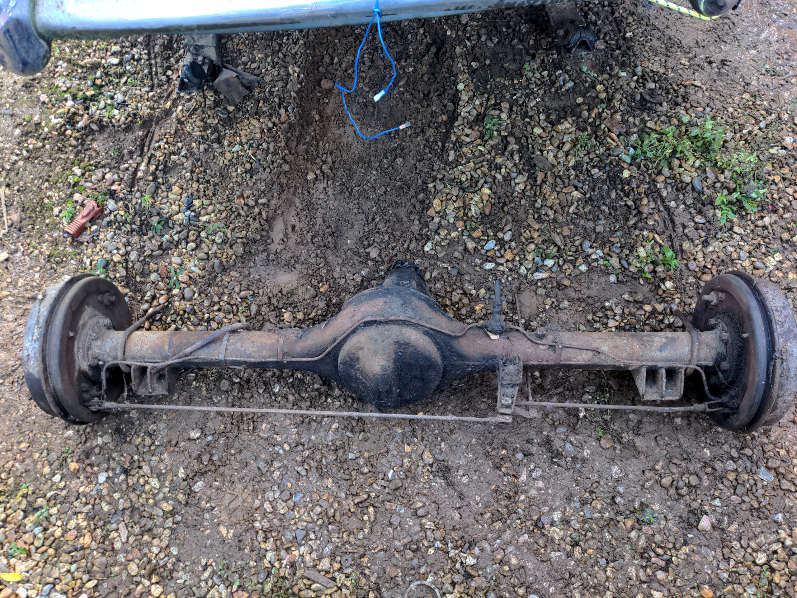
Doing that would be a shame, because it would have written off the axle housing. And this is a complete, original Mark 1A export CKD rear axle in excellent condition. I would rather an entire axle be saved for someone that needs it.
Instead, I rented a van (in which I learned that I don't like modern vehicles, but do like their fuel economy), took a trip to everyone's favourite supplier of unobtainable P5 parts...
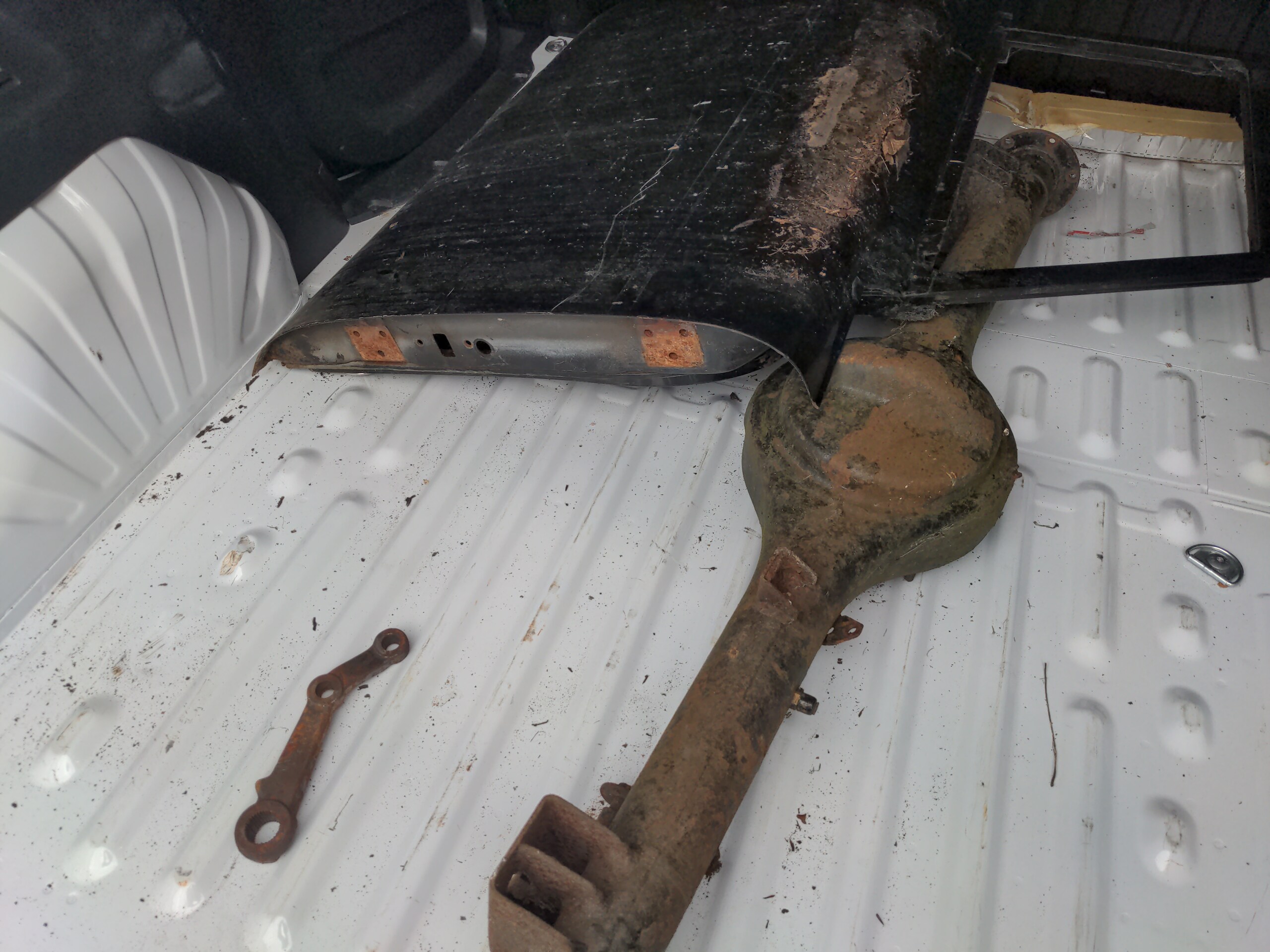
...and came home with an axle housing. And also a Pitman arm, and a door which is in much worse condition than any the one I have. If you wonder why I would specifically seek out a door that is not in good condition...well there are Reasons, and at least one of those will be made clear some time in the next year.
Anyway, while I didn't want to write off an entire axle, I didn't mind cutting up an axle housing that had been kicking around for a while.
Cutting the perches off was easy, because I didn't care about preserving the axle housing itself. It also smelled really good, because this was kicking around outdoors, and so was full of leaves rather than grease. I briefly had the world's largest incense burner in the workshop!
Closer inspection showed that these needed a little repairing; there was a hole on the outside where the metal had thinned out.
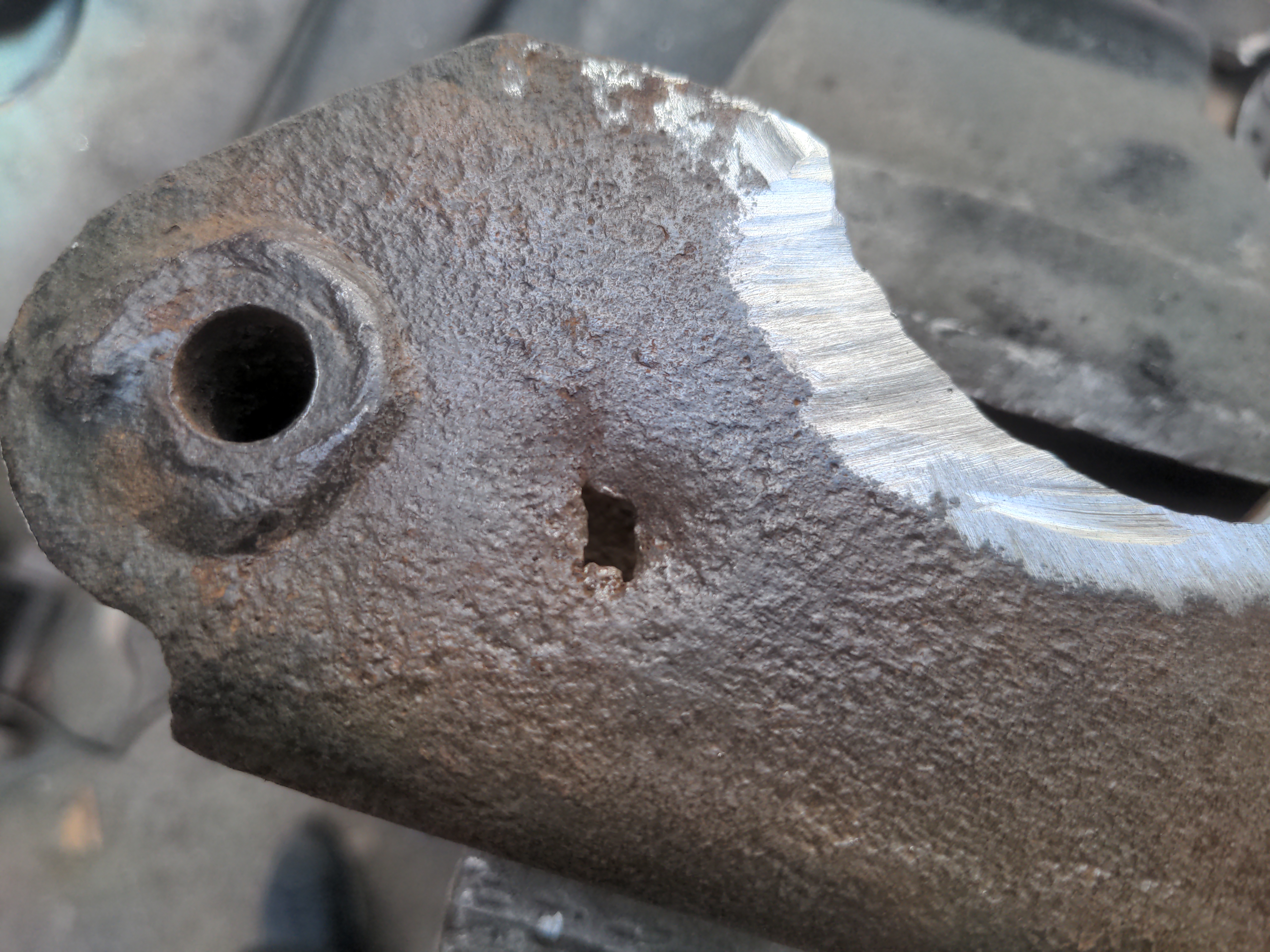
I plated up the inside and filled in with the MIG from the outside, and that was a lot better.
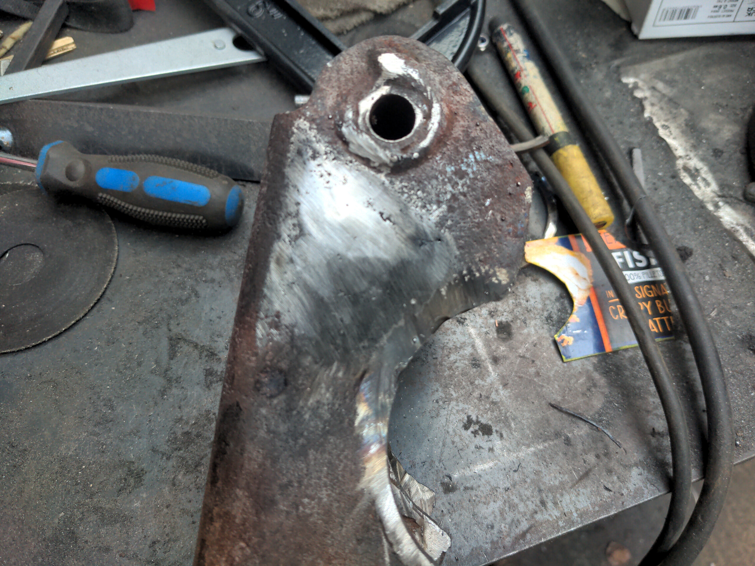
There was a piece on the inside where this had been repaired previously, and badly.
I tried touching up that repair, and then had a side quest upgrading my welder. And after the welder returned I got these perches sandblasted to see what I was actually working with.
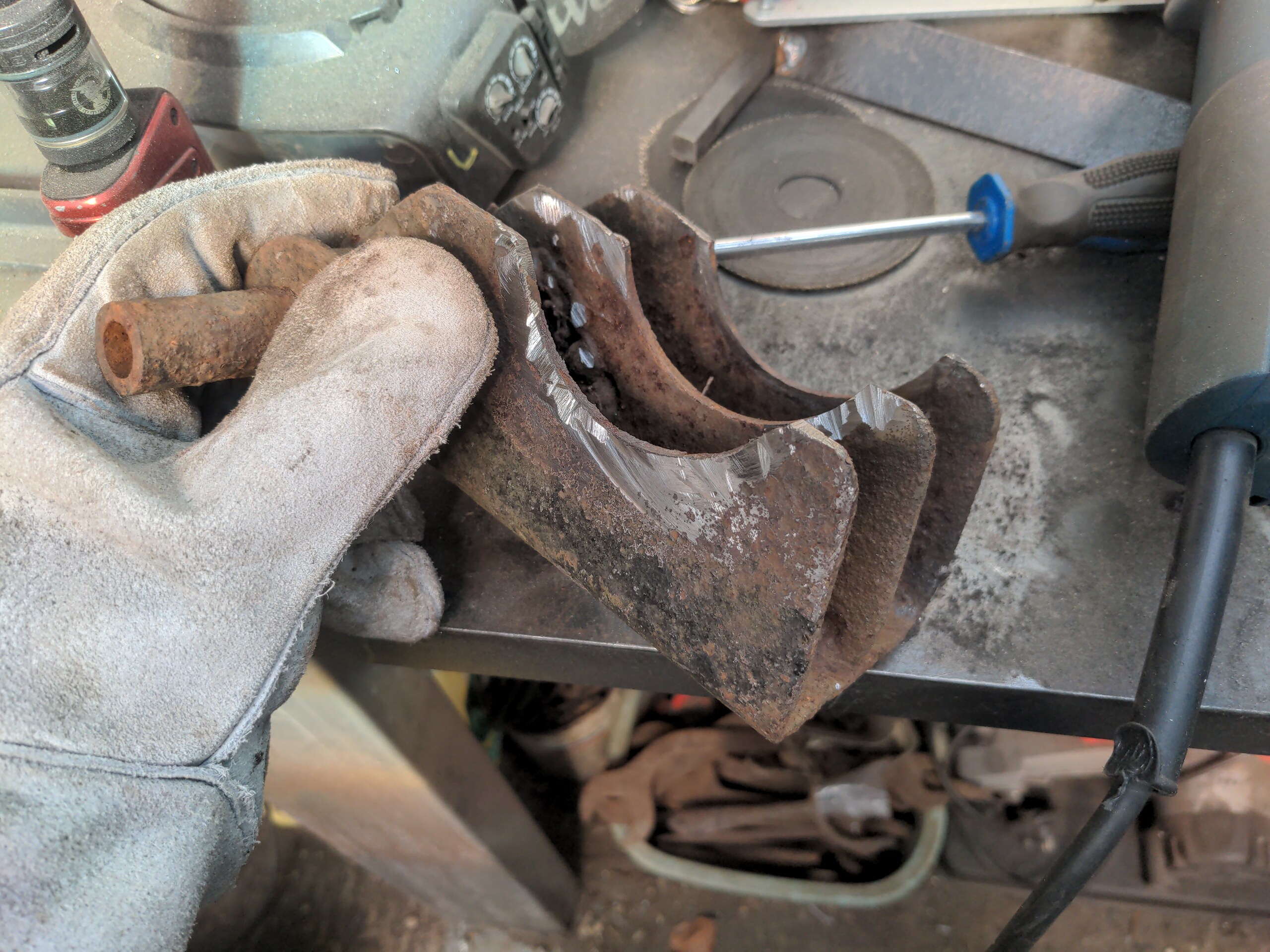
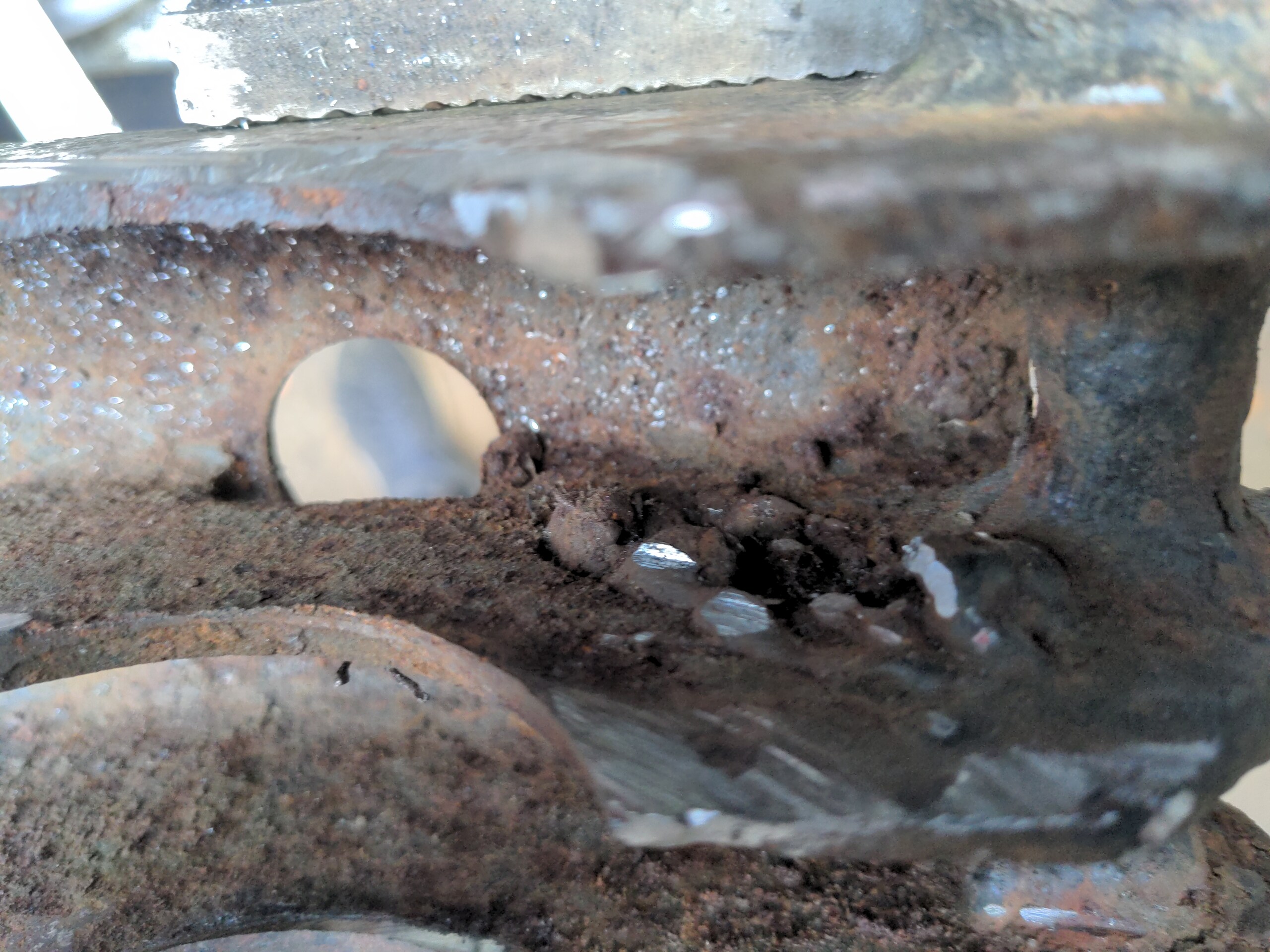
That exposed a flaw in this particular plan, which is that they were Fucked.
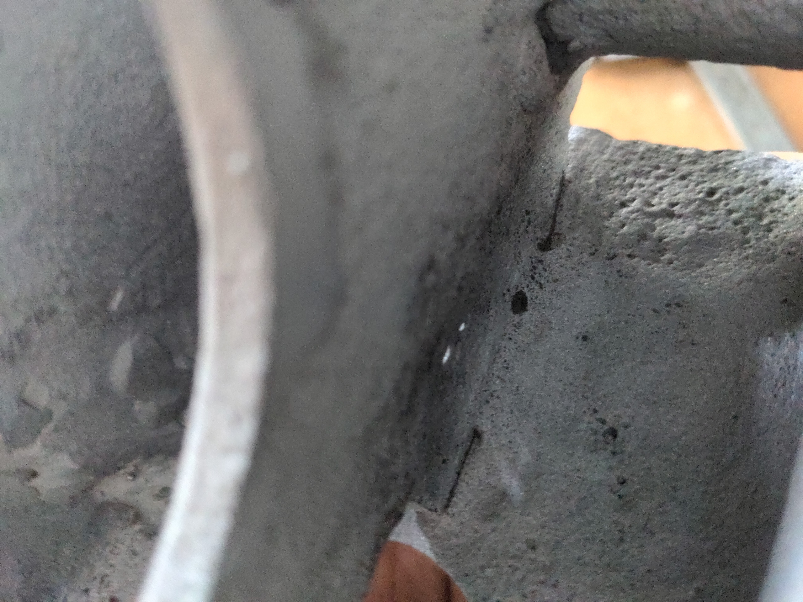
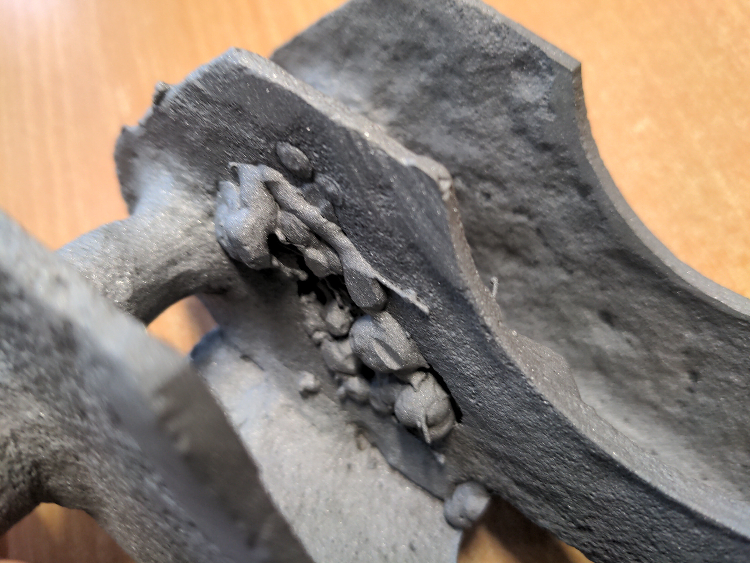
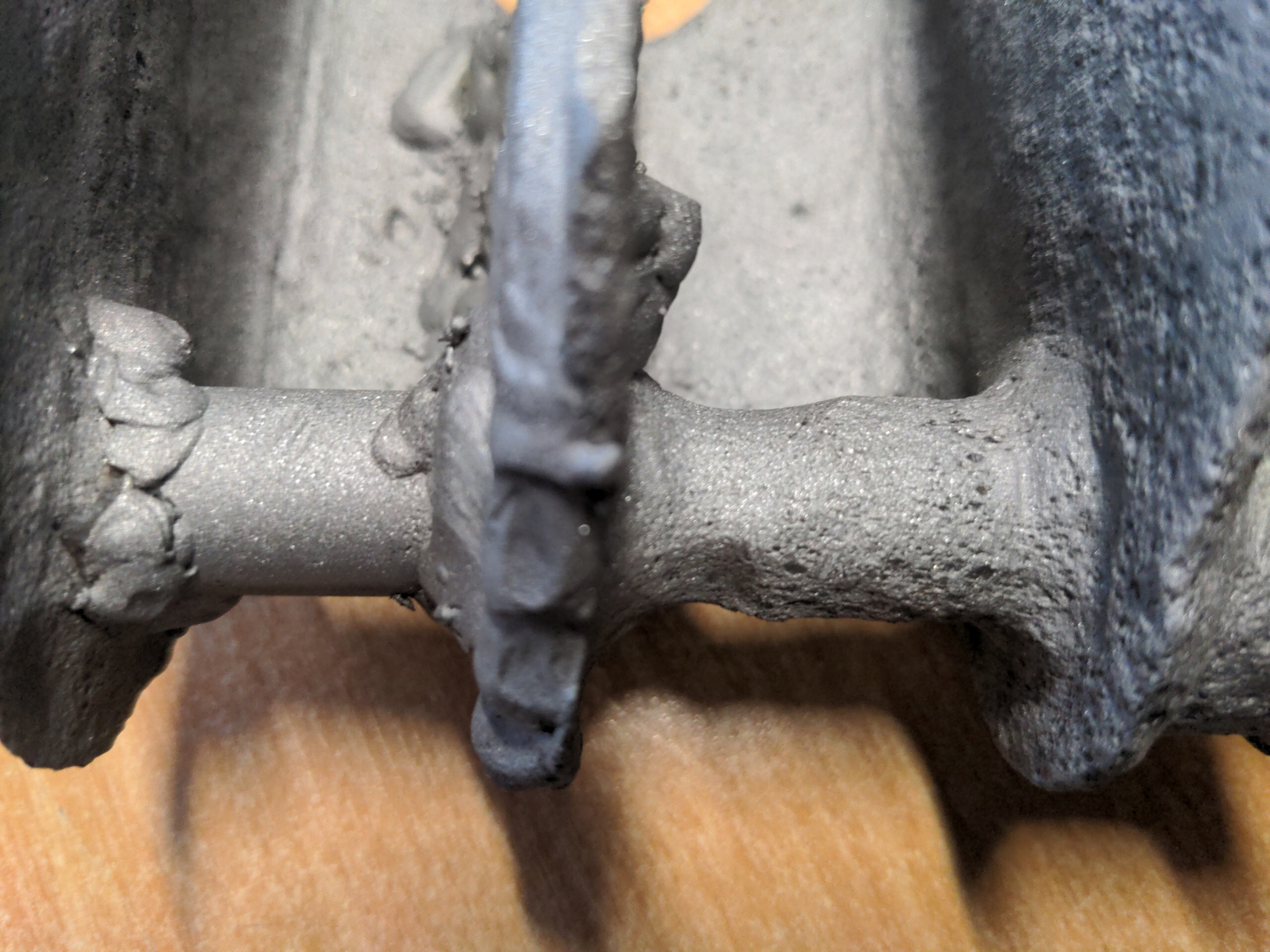
The plate had pinholes, it was dangerously thin in much of the rest of it, the shock absorber mounting rod had thinned down by 4mm in places, and the bad repair was even worse than it looked when I first saw it. If it had only one of these problems it might be salvageable, if I was inclined to do it, and I'd be more inclined to do it if it wasn't impossible to get a MIG nozzle down there at any angle but vertical.
I think it's important to point out that this is not the fault of the man I got this housing from. David is well-respected in the P5 community for a good reason, and I think he's thoroughly honest and nice. This one's on me; I agreed to take it unseen and there was nothing obviously wrong with it at a brief inspection. It was up to me to figure out whether this would be good enough for what I wanted to do with it, and I didn't.
So like, plan B.
Like, Plan B
I'd have liked some other Plan B than the one I ended up with, such as buying replacements, but you can't. They don't exist for the P5, and there's nothing else I could use either. Even if there were other vehicles with 3 inch wide leaf springs for 3 inch axle tubes, I doubt any would have the shock absorber mount built in and in the correct place. Instead, I had to make them. Because how hard can it be!
It starts with some 80x80mm box section.
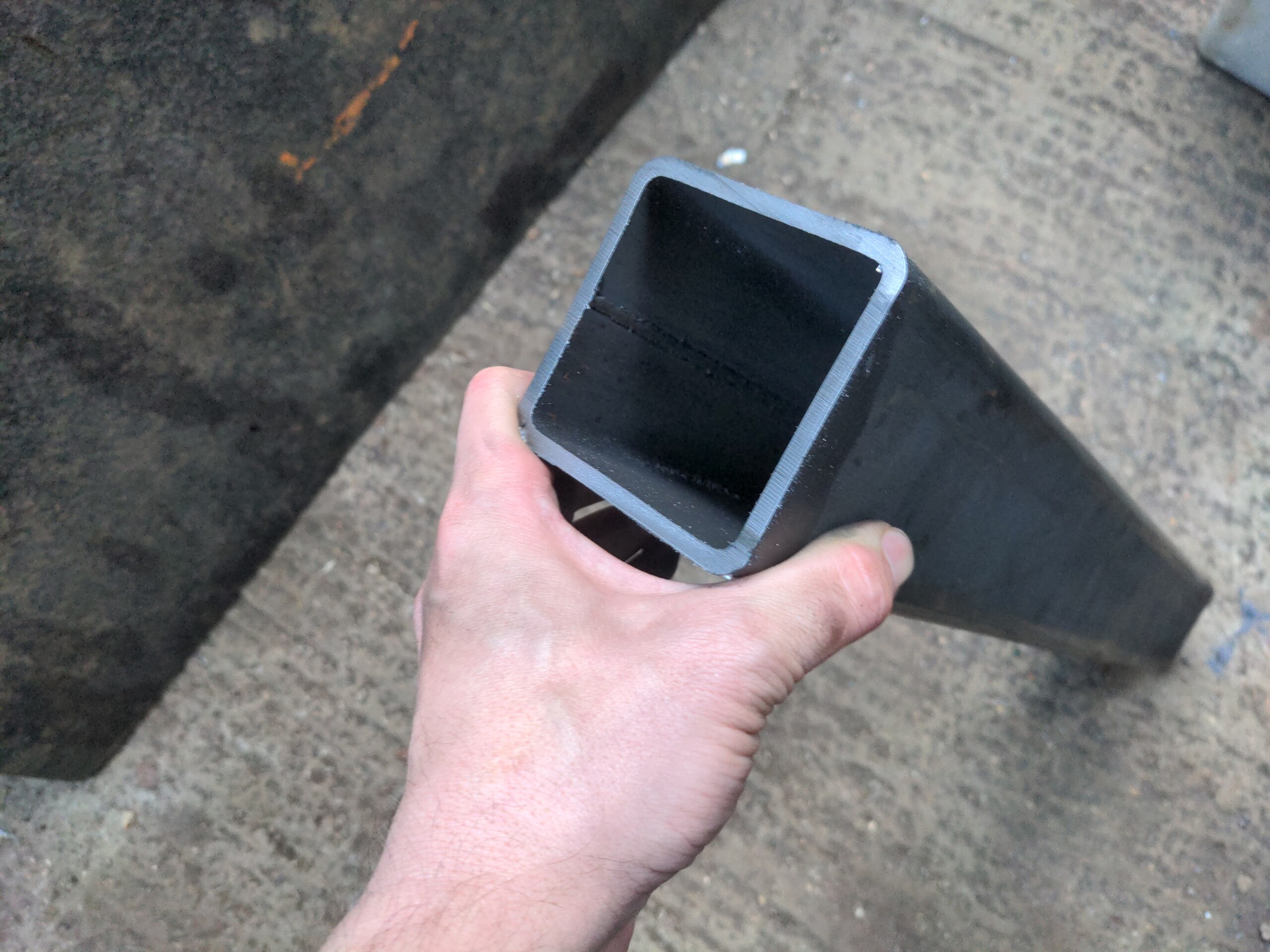
That seems like a curiously metric dimension for a car that uses Imperial measurements, because it is. But I measured the original perches at a hair over 79mm wide. Because of how tight the original leaf spring U-bolts were against the perches, I might have to slot the holes in the bottom plate by half a millimeter; we'll see when I come to fit all this together. I will not bother to recreate the rib in the middle as found on the original perches. It's an unnecessary complication; it isn't needed with steel this thick.
I cut two pieces of the box section, each 160mm long and welded them together.
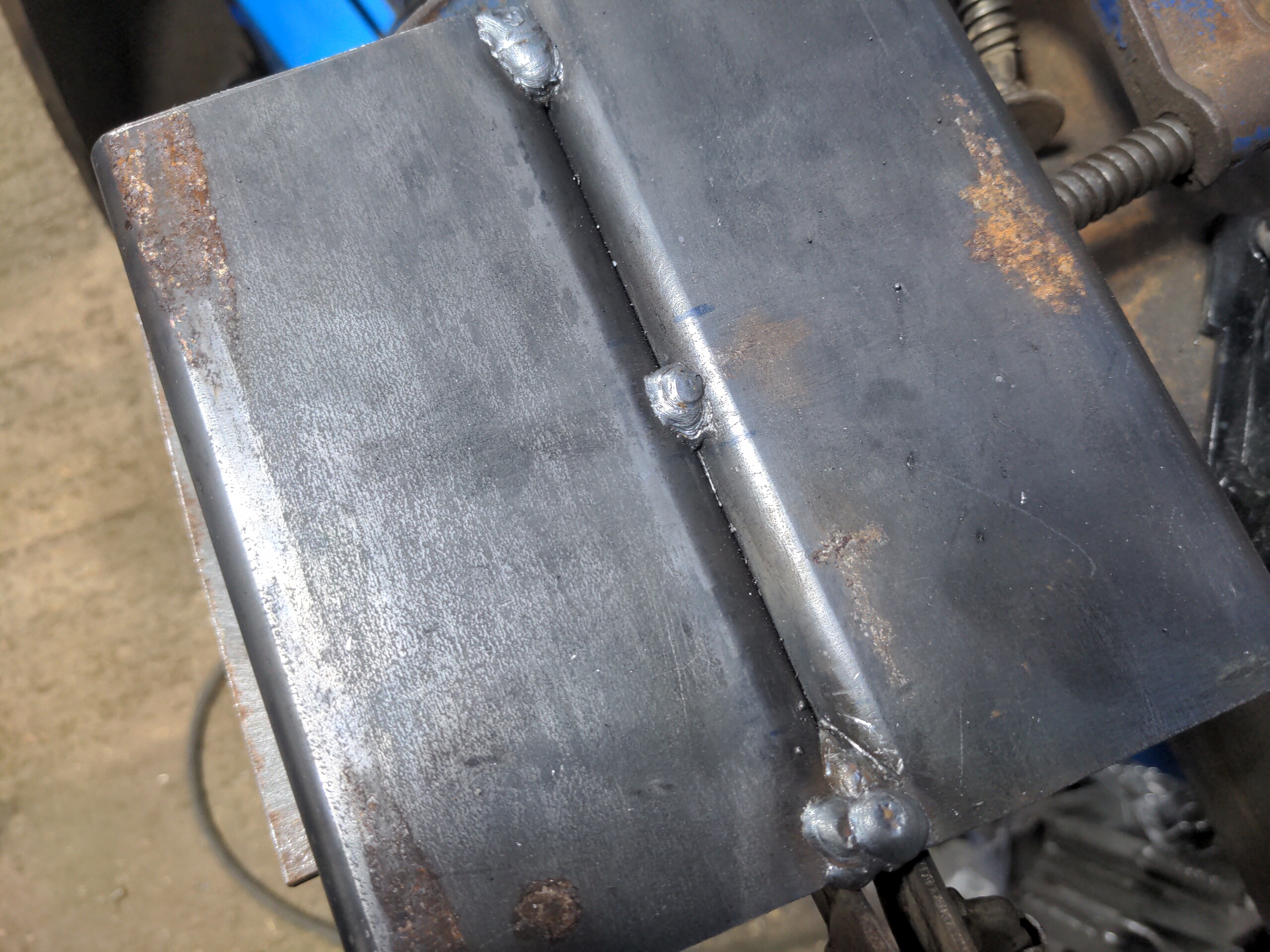
Flatness is important here! Before welding them, I put them on a massive piece of half-inch-thick steel plate, clamped them down with three clamps, then clamped them together with two more for good measure. This eliminates any possibility of heat distortion on several axes. It was probably overkill, but those things were kicking around the workshop and I might as well use them.
I had to grind these welds flat later; this will be going into the mill for drilling.
Next, I marked up and punched holes. Two of these are where the shock absorber mount will go through.
Here's the basic plan:
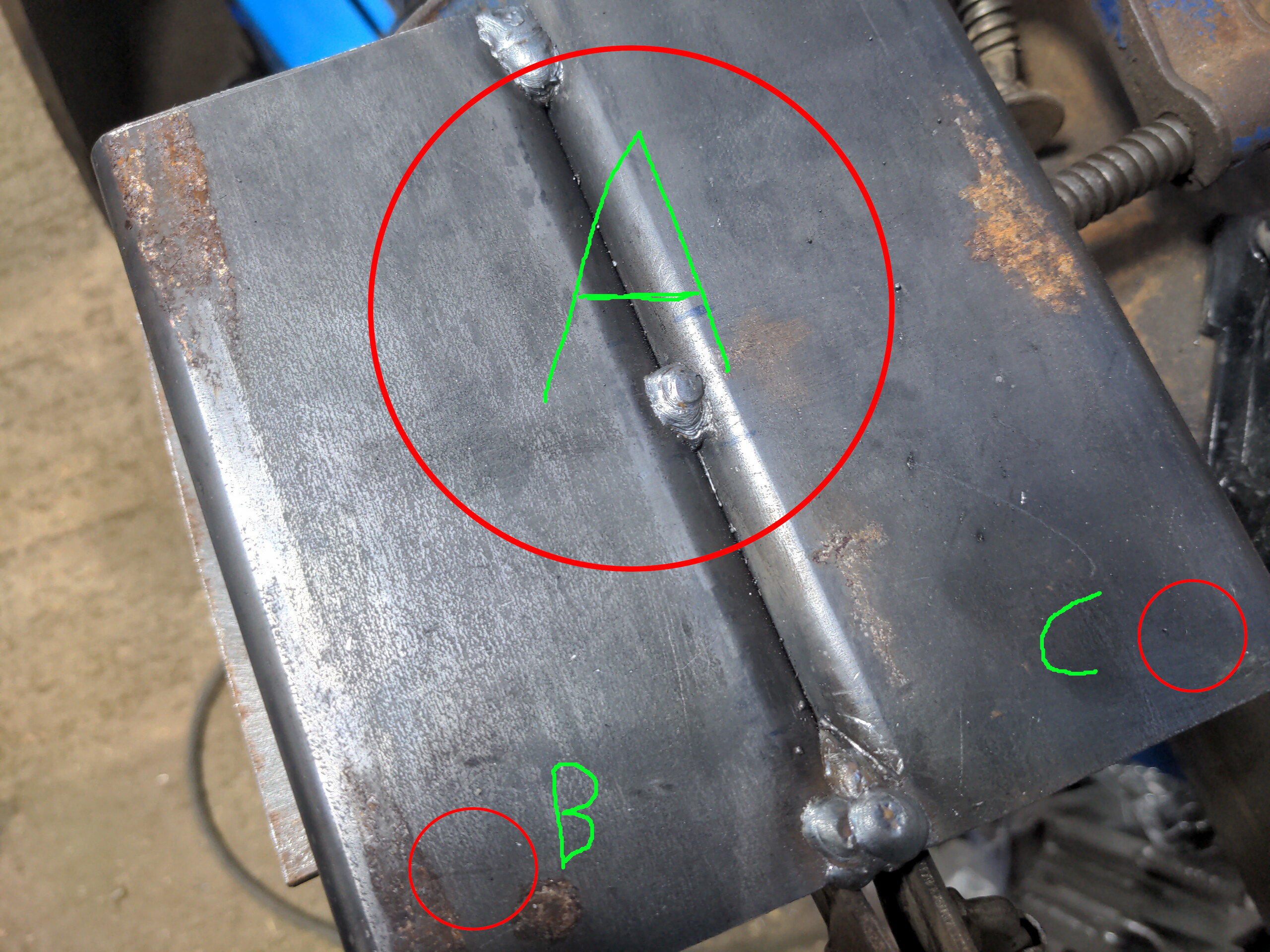
And here's something I threw together in FreeCAD to maybe better show you what I mean:
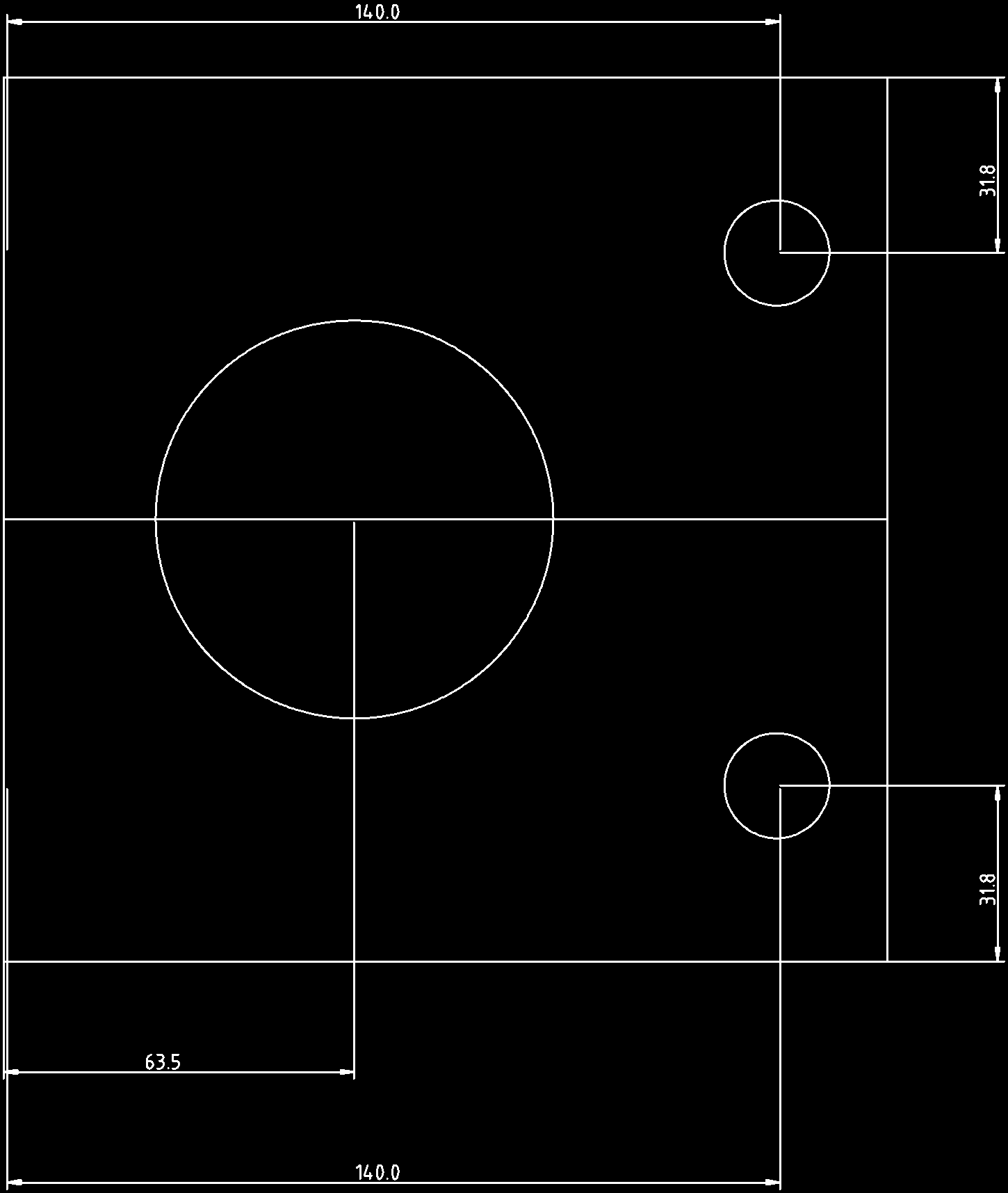
The big hole in the center is to form the curve where the perch welds to the axle tubing. It will be drilled with its centre right at the join of the two pieces of metal. That is offset from the left edge by 63.5 millimeters. I measured the correct position for the two 19 millimeter holes (B and C in the photographs) as 31.8mm from the outside top and bottom edges, and 140mm from the left edge. (And if you are surprised at the decimal precision: I used a digital vernier for most measurements, and I don't believe in throwing away precision until the very last moment.)
The idea for the big hole was to send a 76mm (3 inch, which 75mm is not) TCT hole saw in a single pass. Of course, if you look at this photo of what hole-sawing removed from this...
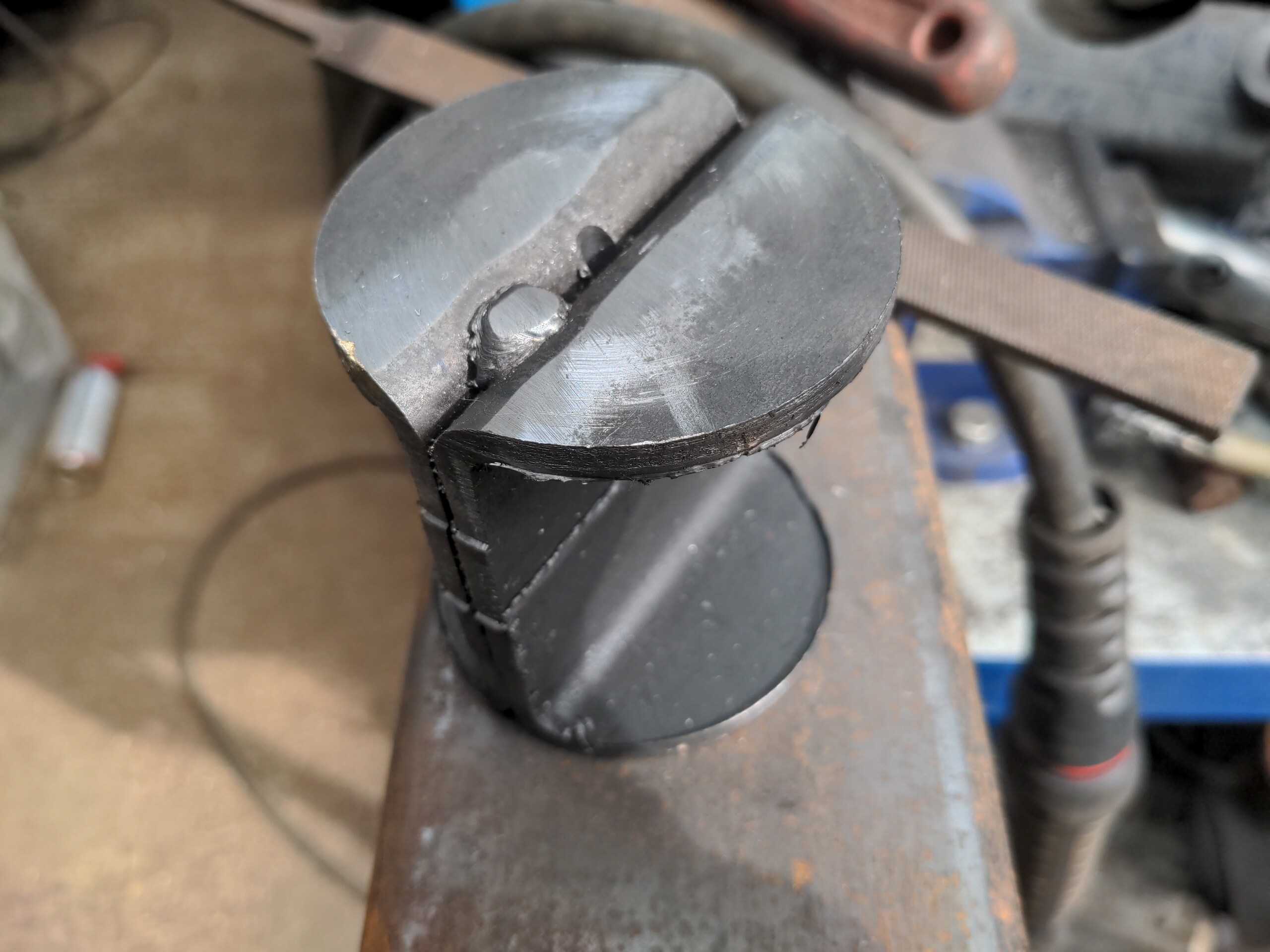
...you'll quickly work out why that could not possibly work (hint: hole saws are not arbitrarily deep). Instead, this had to be done in more than one pass. First, the TCT started the cut, and went down as deep as that could. Then a somewhat-deeper Starrett hole saw (FCH0300) followed it to extend the cut deeper. I actually bought the Starrett one as a backup to the no-name TCT in case the latter exploded; I wouldn't have been able to complete this mini-project without it.
Then, without moving the workpiece on the bed of the mill, the hole saw was swapped for a long 6mm drill bit. That went through all the way to give a marker on the other side, so that the workpiece could be flipped over and the hole saws sent through again, using the hole from the 6mm bit as a guide. That still didn't cut all the way through, but the remainder was so small that the above piece could be knocked out with a hammer.
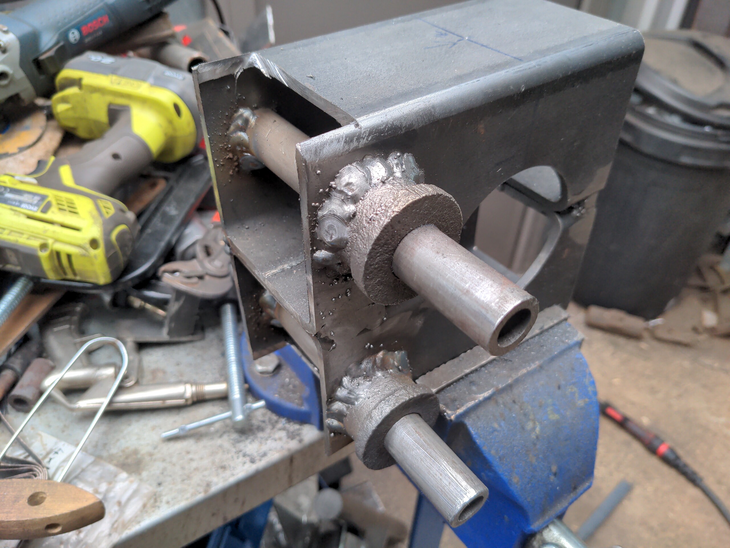
The 19mm holes were made in the places they should be made in the obvious way, and I shoved some correctly-sized tubing through them them. This was 19.05mm tubing (it's fine, it went through with only a little persuasion), with 3.25mm walls, which makes it just the perfect size on the inside (12.55mm) to shove an M12 bolt through it.
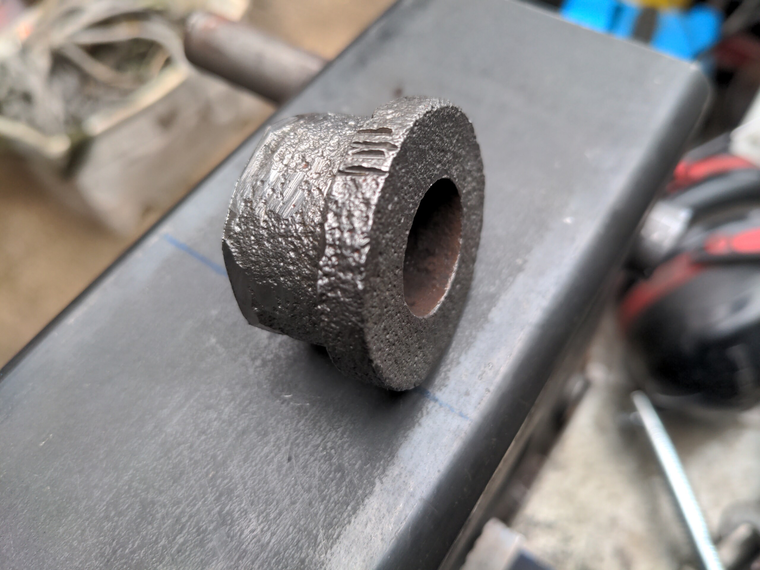
I needed to reproduce something like the donuts that go over the bottom of the mounts. I could have turned these up on the lathe, but it was less effort to just cut off the originals. That means that the rear axle on the P5 will have at least one actual Rover part!
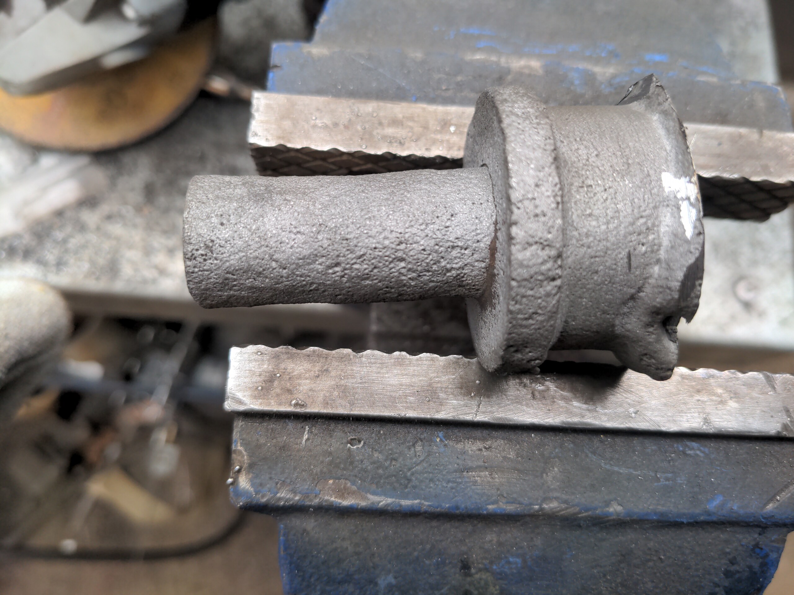
The donut I wanted is not welded to the sticky-out bit, but it might as well have been. It took some bribes with the oxy propane torch (yay dangerous toys) and a big hammer to get them separated.
With that all welded up at the end of day 1, it looked like this.
That's fundamentally complete! You'll notice that I haven't separated them yet. This is not an accident. I take heat distortion much more seriously than I was this time last year. Welding generates lots of heat, and angle grinders generate somewhat less. Keeping them welded together should mean they reinforce each other against it. I didn't separate them until there was nothing more I could do without separating them, and after they were separated I didn't cut the bottoms of the boxes out until there was nothing left to do.
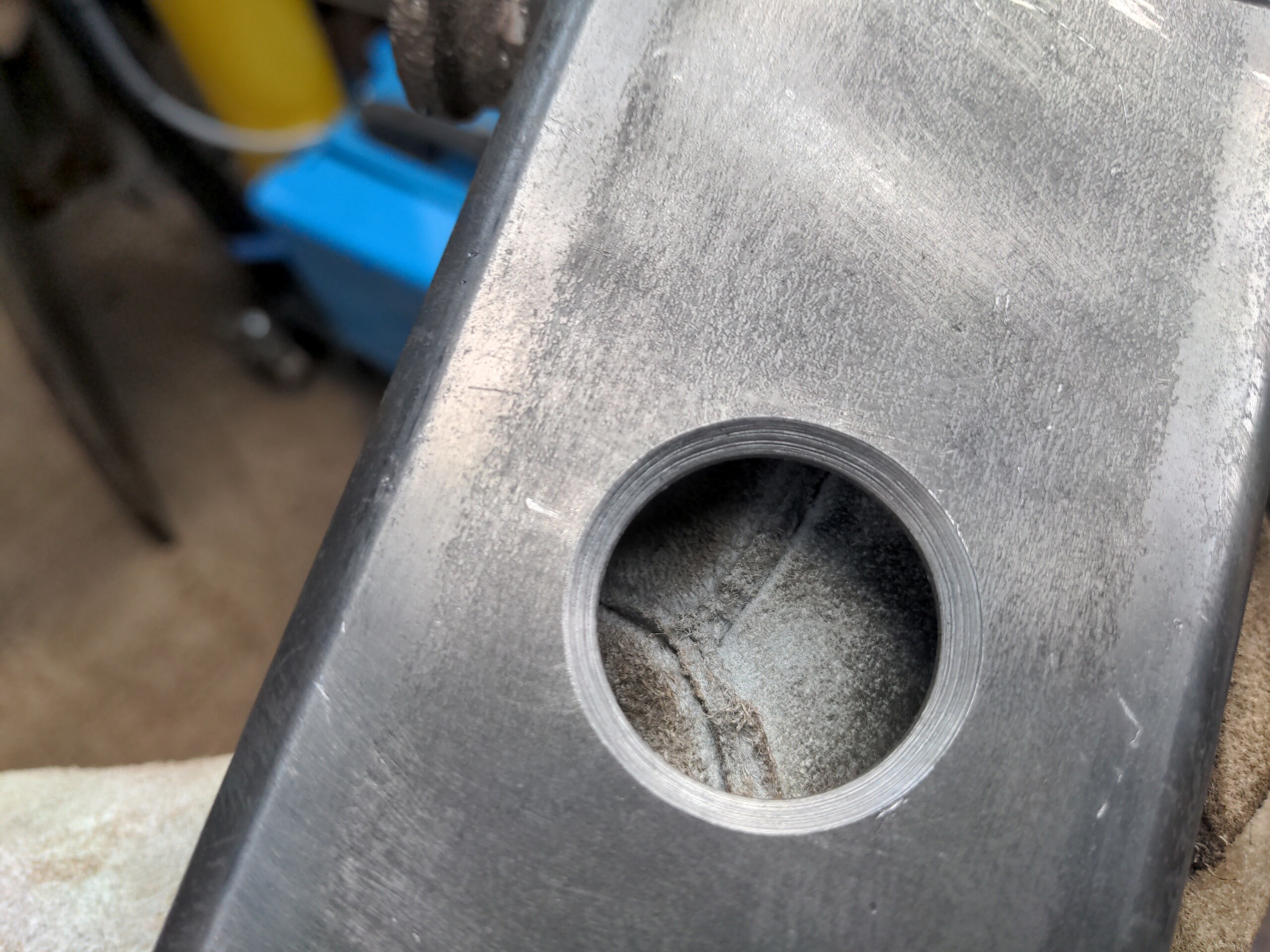
There was one more hole to drill: the locating hole for the leaf spring. That is on the top, in the center on the left-right axis, and at the same 63.5mm front to back (offset from the opposite end to the shock absorber mount). This needed a 29mm hole. I made that hole look nice with a big (40mm) countersink .That might not be necessary, but the originals had it and it looks nice.
I could have just separated them here and called it done. But I wanted these to look right, so I spent a few more hours with a grinder on day 2 to shape them and tweak them till they looked nice (and somewhat like the originals, with the help of a marker pen and a crude cardboard template). And by 3pm, even factoring in waking up an hour late because of the clocks changing...
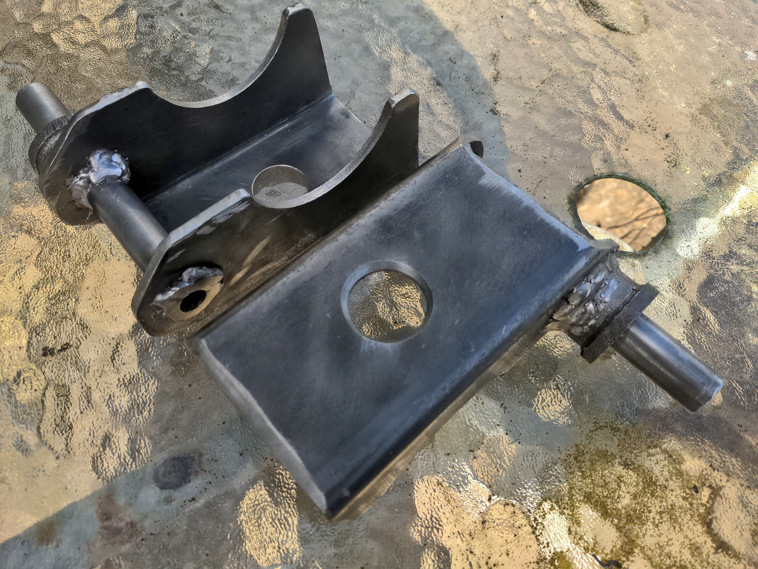
...I had some Rover P5 leaf spring perches, ready to be welded on to a completely different axle housing. I am more than happy with how those turned out. I wouldn't look like a real fabricator if you stood back 20 feet and squinted, but this is definitely a nice accomplishment for someone who has no actual clue what he is doing.
See you next time. :)
Thanks to Maurice for the help working the mill and for some quick thinking that saved me at least an entire day!