A new axle for the Rover P5, part 2: the housing
I know what you're thinking. It's something like "Lewis, a Rover P5's prehistoric rear axle will explode if you put 350 horsepower through it". And you're right!
There are lots of ways I could build a rear end for the P5 capable of handling LS power. Probably the sensible thing to do would be to chuck a BMW E60 subframe under the back and call it solved. That'd be cheap, parts would be available long after I wrap the car around a tree, and the fabrication doesn't scare me too much. But while I'm hardly shooting for originality here, fully-independent rear suspension crosses a line for me where the car wouldn't really be a P5 anymore.
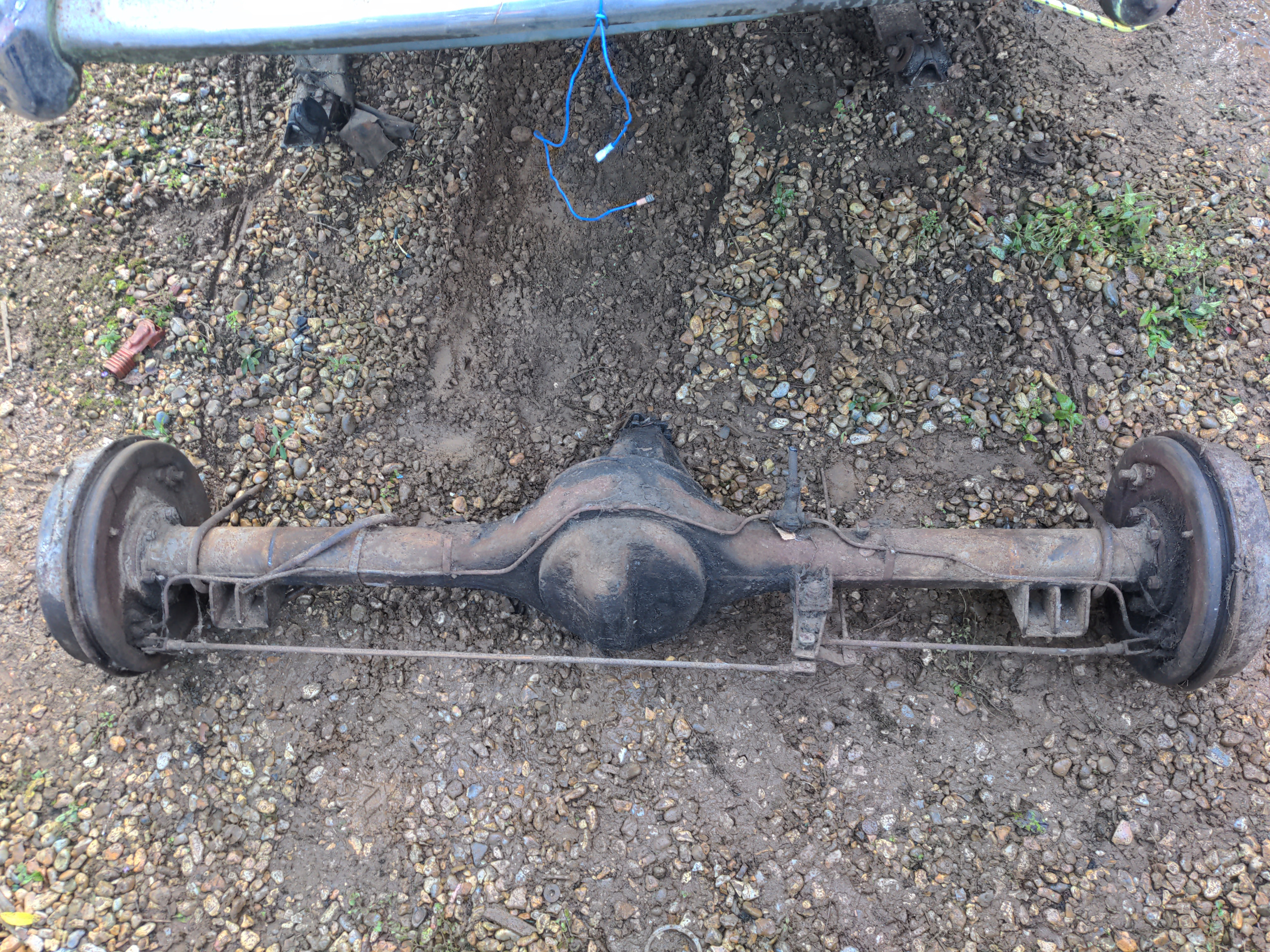
Instead, I wanted a live axle like the one that came out of of the P5, and the inevitable conclusion of all discussion of live axles is the Ford 9-inch.
The Ford 9-inch is a design that goes back to the late 1950s, was phased out in the mid 1980s and was fitted to millions of cars and trucks in the United States in those 30-ish years. It is legendarily strong; a completely stock axle is safe up to about 400 horsepower, and axles built with the right aftermarket parts will survive "you'd have to be utterly stupid to use this on the road" horsepower. And the aftermarket is amazing! It's such a sound, well-tested and well-loved design on the other side of the Atlantic that you could build a complete brand-new "Ford" 9-inch axle without a single Ford component, if you were mad.
So here is my starting point.
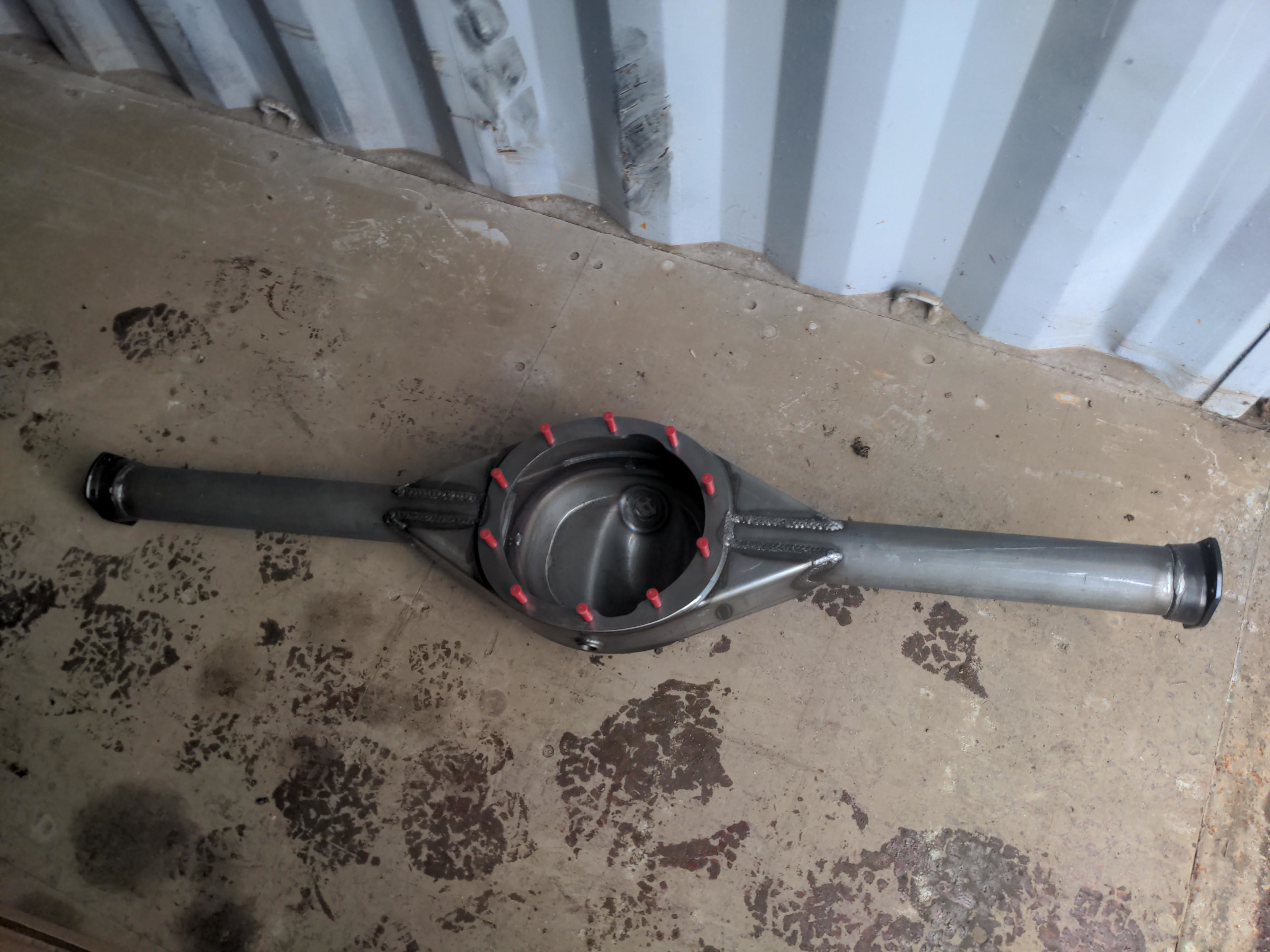
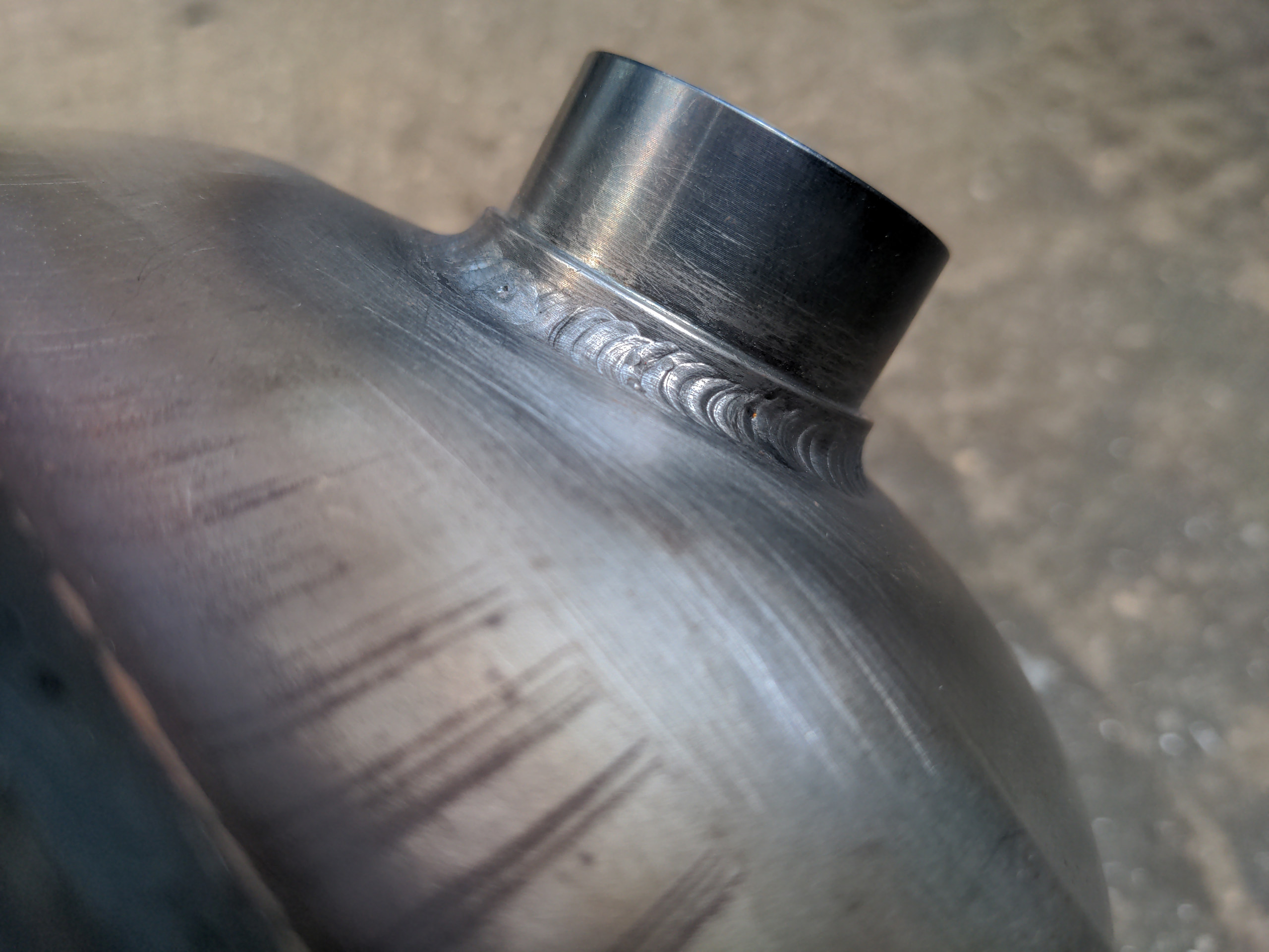
This is a Ford 9-inch axle housing that does not contain a single Ford component. Instead of any Ford components, it is a Strange Engineering heavy-duty housing, welded to 3" CDS axle tubes, with Strange Engineering "late Big Ford" housing ends. It's a work of art, the work to assemble it into the housing is perfect, and it is good for more power than even an unreasonable person would try to squeeze out of an LS1.
I wish I could boast that this housing was my work, but it isn't. I can stick two pieces of metal together with a welder such that they don't break, but I can't do that while holding an axle housing and axle tube dead straight on all axes. And even if I could the welds wouldn't look slightly as nice as this.
It was instead built for me by Hauser Racing, to the correct width to fit under the Rover P5. I love Hauser Racing! They're not a mere importer of parts, though they can in fact get all the parts from the States that I could possibly want. They know the things they sell inside and out because they build hardcore drag cars, and by the way are literally a drag racing team too whose founder is a bit of a legend in that world. When I call them, I immediately have someone on the other end who can answer my technical questions. Most of those questions were basic stuff as I navigated the new-to-me world of overkill rear axles, so they're also very nice for putting up with me.
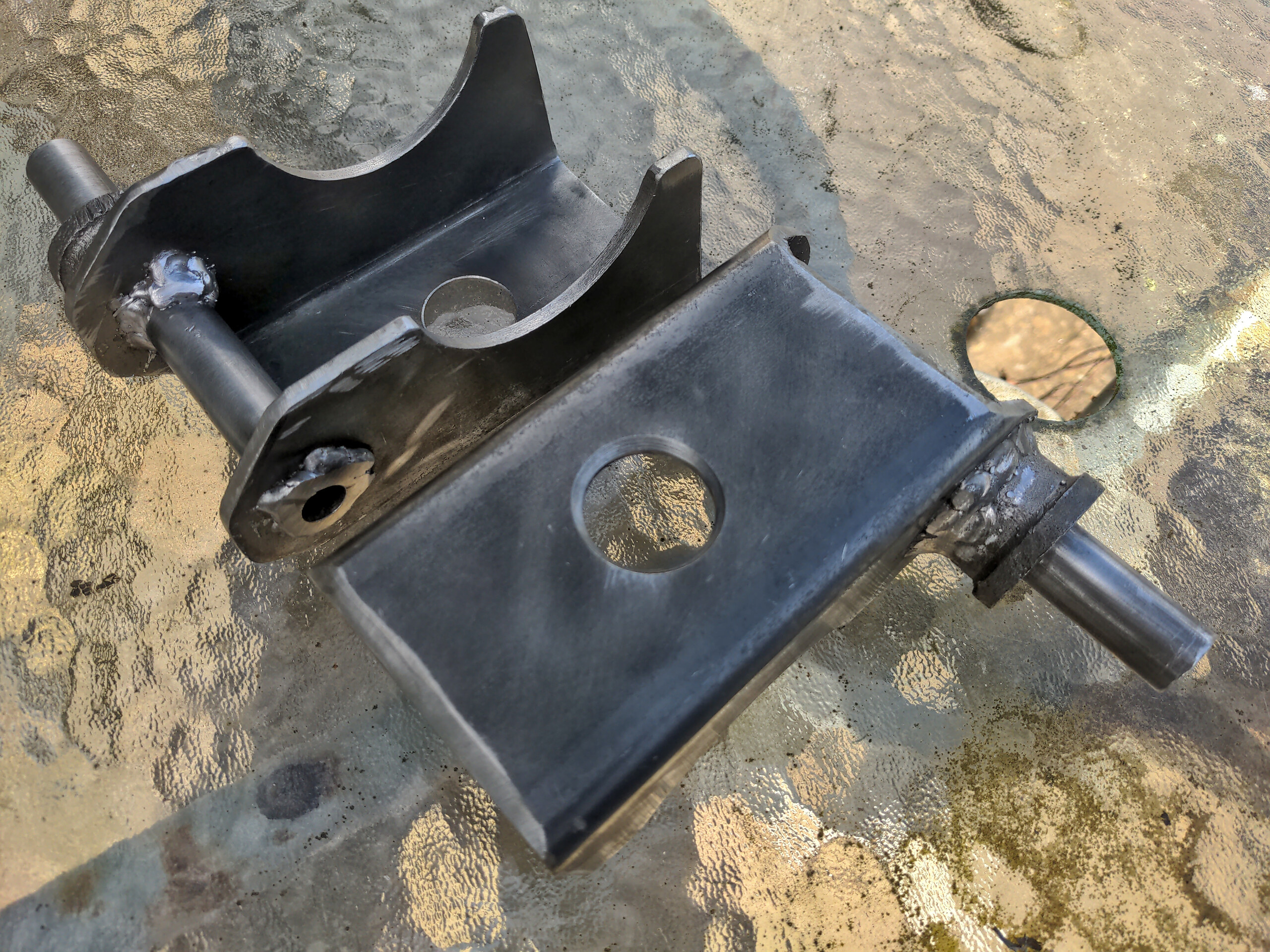
So I had a beautifully-welded axle housing, and I had two things to weld on to it. Both of these were spring perches that I made in part one.
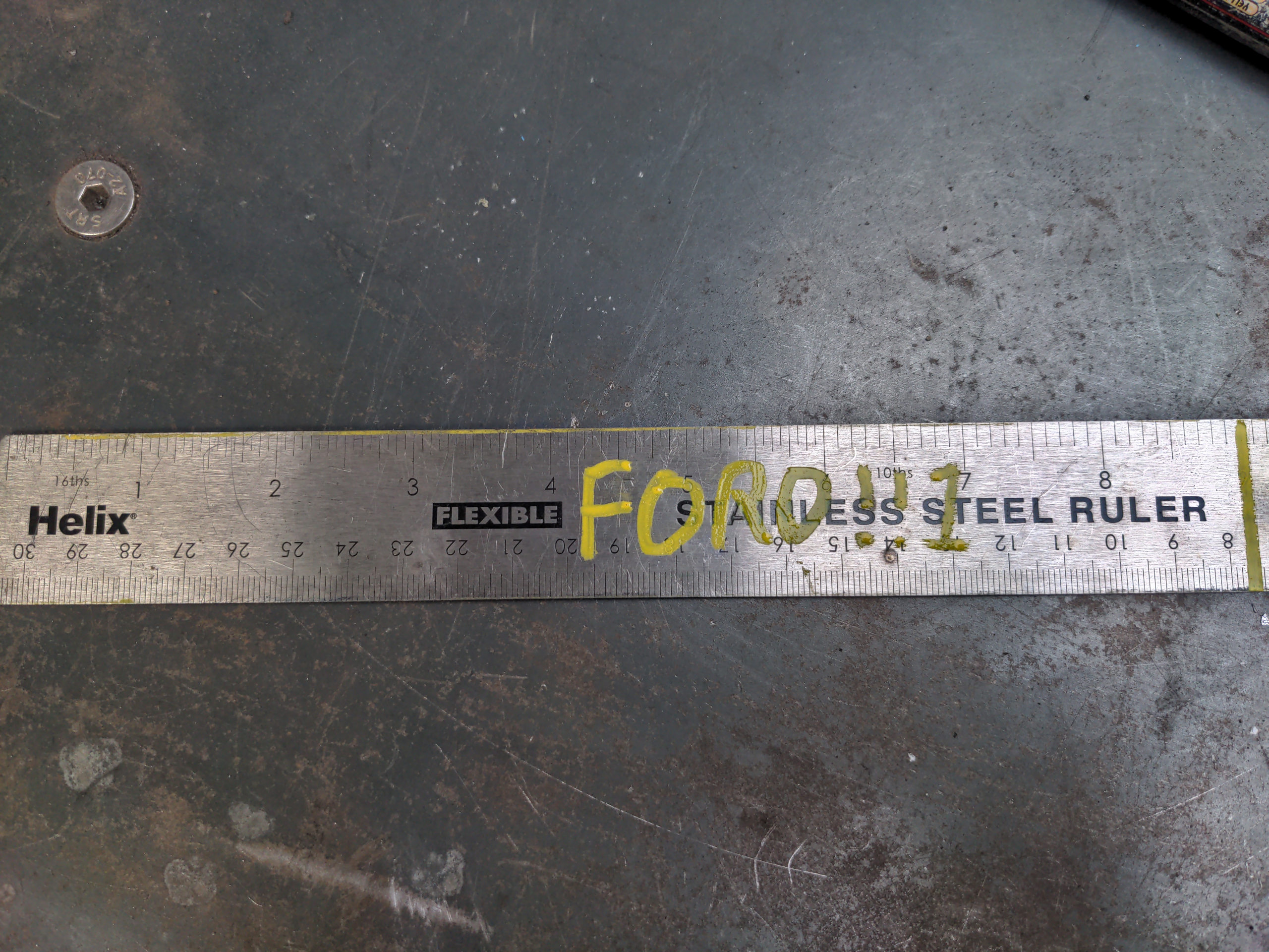
The first job was to work out what their position should be, and the easiest measurement to take is from the outmost edges of the spring perches. I measured this on two different Rover axle housings: my original one after I took it off the car, and the one that I got from David Green. These actually measured slightly differently. My original measured 1140mm, and the one from David Green measured as 1145 mm. A curiosity was that the one from David Green had one spring perch 5mm closer to the ends of the axle tubing than the other, for unclear reasons (it does not look like it was ever chopped off and welded back on again, ruling out the obvious explanation).
To settle it, I took a couple of measurements from my P5's shell; these suggested that 1145 was probably correct for my car. It might not be for yours. The easiest way to do this is to measure the distance between the outside edges of your chassis rail immediately above your axle, subtract the width of one chassis rail (this gives you the distance between the centres of your chassis rails), then add the width of one of your leaf spring perches (this is 80mm for mine; it's probably 79mm on the originals).
And I know, it seems absurd to chase millimetres that the car wasn't made with in the first place (see also the 5mm difference between two different unmodified axles!). The slop in the suspension of an old leaf-sprung car seems like it'll outweigh all of this. But two things:
- Polybushes and a radically different rear leaf spring bush replacement (this last to be discussed in a future post) will hopefully engineer much of the forgiveness out of the rear end, reducing the tolerances I have to work with;
- If you don't have the resources of a real fabricator (this is mostly me and an angle grinder and a 40 year old bandsaw and a free MIG welder) you are going to end up with some things out of tolerance no matter how hard you try. So chase millimetres while you can and don't use up the tolerances when you don't need to!
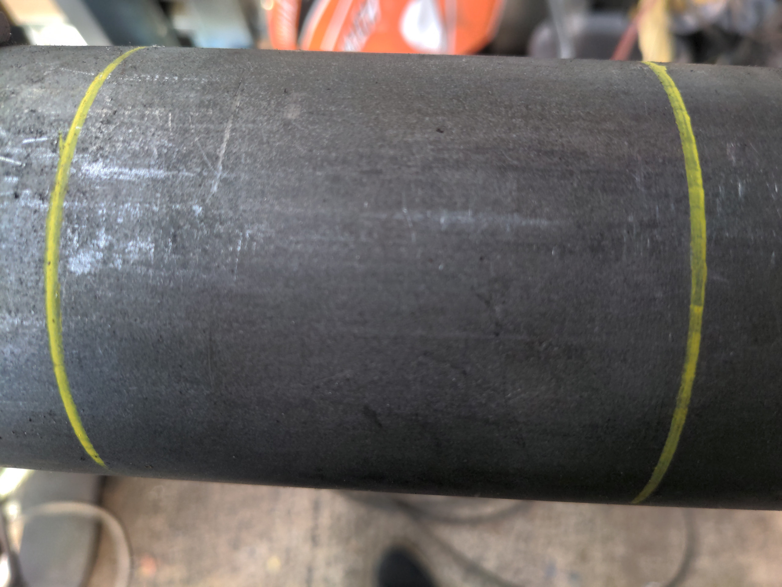
My axle housing is 1384 to its very ends. So that means the outside of my spring perches needed to be 119mm from the Ford housing's axle ends. That's easy to do with a set square. To make life easy for myself, I temporarily held the perches in place with magnets, validated the measurements then marked along the perches' sides with a paint pen.
That means that I can eyeball the perches' proper position when I put them in place to be welded. That is useful because there's one more thing to be set up, which is their angle. These must not be dead flat on the bottom edge! My P5, the original P5, and just about every rear-wheel-drive car has a 3 degree downward tilt (towards the rear) to the entire drivetrain. To eliminate vibration, the two faces of the propshaft must be parallel. That means that we also must point the input shaft of the axle slightly upwards, by the same 3 degrees as the drivetrain angle. You can do this with shims after the fact, but I found out (thanks Hauser Racing for fielding my dumbass calls!) that it is much better to do this by positioning your leaf spring perches appropriately.
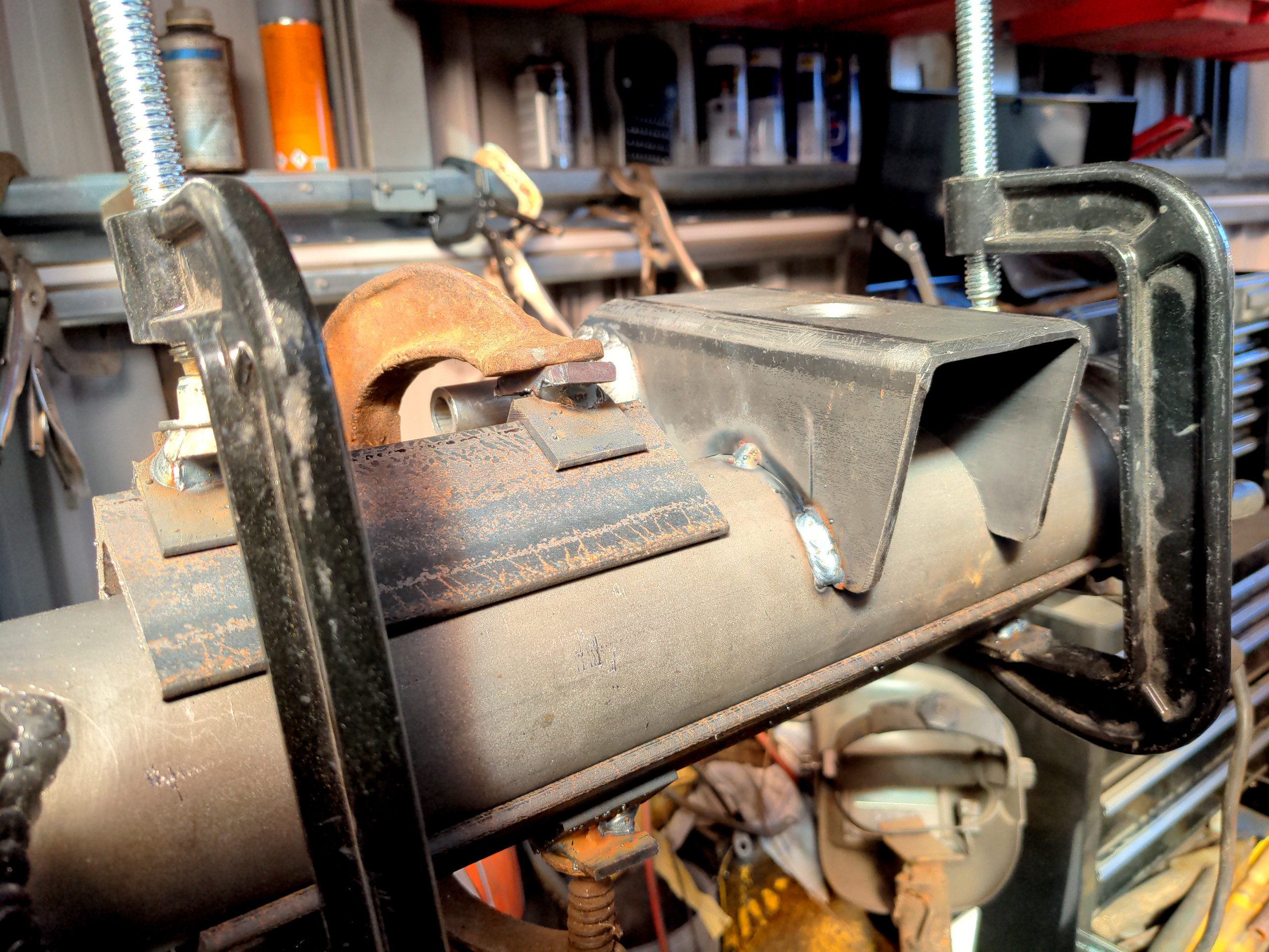
This is fiddly to set up; a massive vice to hold your axle still and a calibrated digital level are your friends. And this is why I marked the left-to-right location of the perches first. It meant I could eyeball that dimension any time I needed it and concentrate on getting the rotation right.
Next up was welding them on. The enemy here was heat distortion. Welding generates a lot of heat, and heat causes metal to expand, contract, and move. This often doesn't matter for things that aren't axle housings; you can always bash it back into shape or just start again. An axle housing doesn't have much tolerance for misalignment, I don't have the means of beating it back into shape accurately, and "start again" would make me four figures poorer.
To solve this problem, here is a piece of angle iron sitting atop a piece of tube.
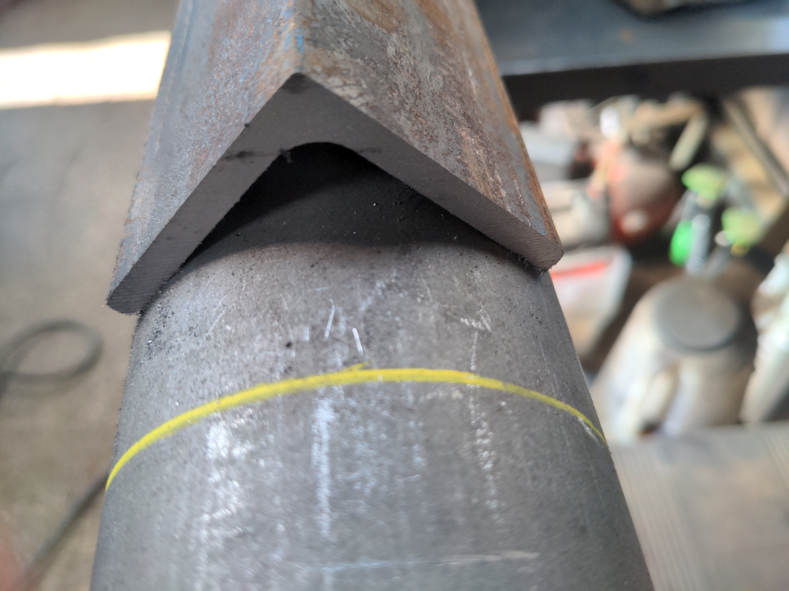
This is how angle iron will always want to sit on a cylinder. You can exploit this property should you ever need to draw a dead straight line on a piece of tubing; just put a piece of angle iron on top of it and draw along its edge. You're welcome! My theory was that you could also exploit this property to keep a piece of tube dead straight while welding it; if you clamp a massive section of angle iron really tight to a piece of tube it will resist distortion on two axes.
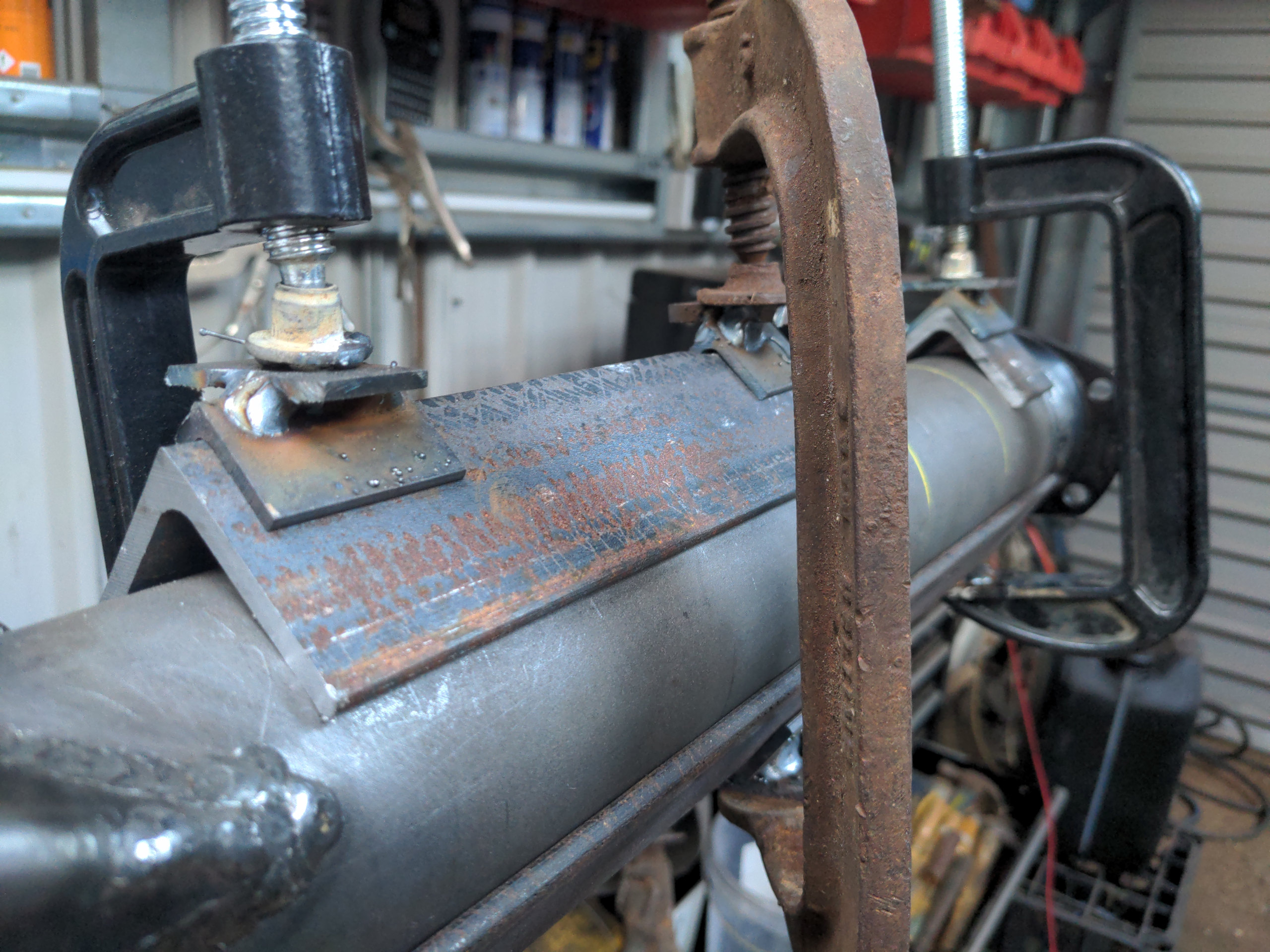
If you clamp a massive piece of angle iron to one side of the tube, and an extra piece to the other side, and you only weld a little at a time and let it cool fully, you should have pretty good odds of avoiding heat distortion.
That's the theory I probably didn't fully think through! But even now it seems sound to me. We'll find out when my driveshafts do or do not fit properly.
G-clamps do not naturally want to sit on the apex of a piece of angle iron. I could have welded little flat pieces onto the angle iron. But then I might distort the angle iron while welding it, and it would no longer be as completely straight as I needed it to be for this purpose. Instead, I got some scraps out of the "might be useful some day" bin and made these little adapter pieces.
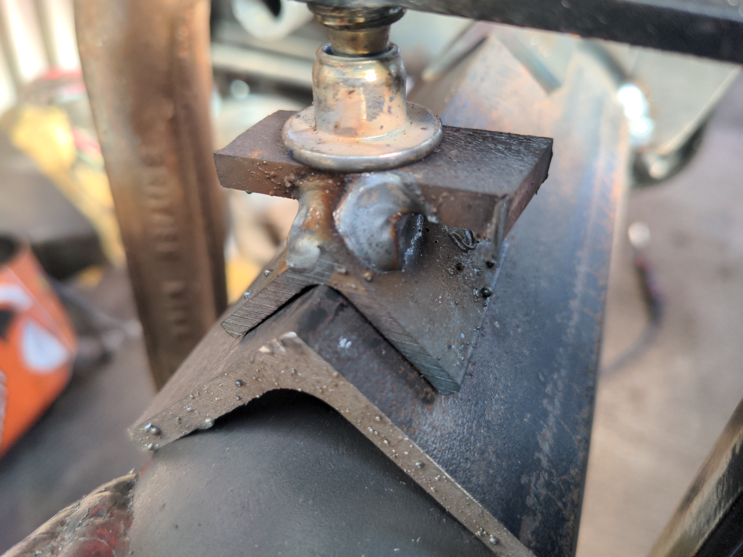
It doesn't matter if these bits distort while I welded them, because they aren't references. They just need to sit on the bigger piece of angle iron tightly enough that the bigger piece wouldn't move, and to give a mostly-flat edge for the G-clamp to clamp to. I only had one G-clamp that was actually big enough to hold one of these adapters on each side. Instead, I MIGed some blobs of metal onto one of the faces of two of my worse, cheaper clamps and that stopped them from sliding off the apex when I tightened them down.
The first perch took the best part of a day, but that included making up those little adapter pieces. It took about 20 minutes for each weld and the surrounding tubing to fully cool to ambient temperature. It was slow going, but slow going was much more fun than writing off a very fancy axle housing. But when I was done, with all the welds tidied up...
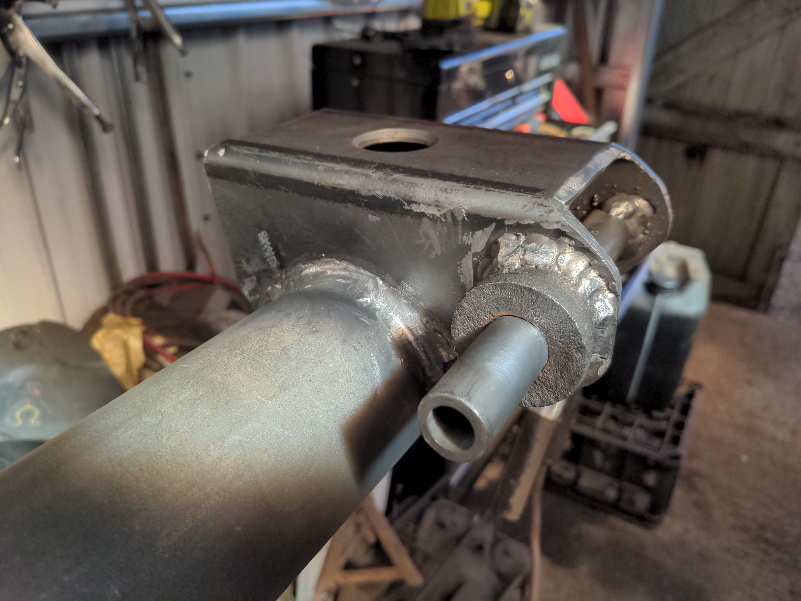
...it looked pretty damn sweet. I don't normally bother smoothing out welds like this; I don't much care to pretend that I'm a better welder than I really am. But in this case I had to smooth out the welds at all the corners, otherwise the U-bolts won't clear. And if I'm doing that some Lewis-logic said I might as well get completely carried away and do all of the welds to make them look pretty.
Anyway, do all that twice...
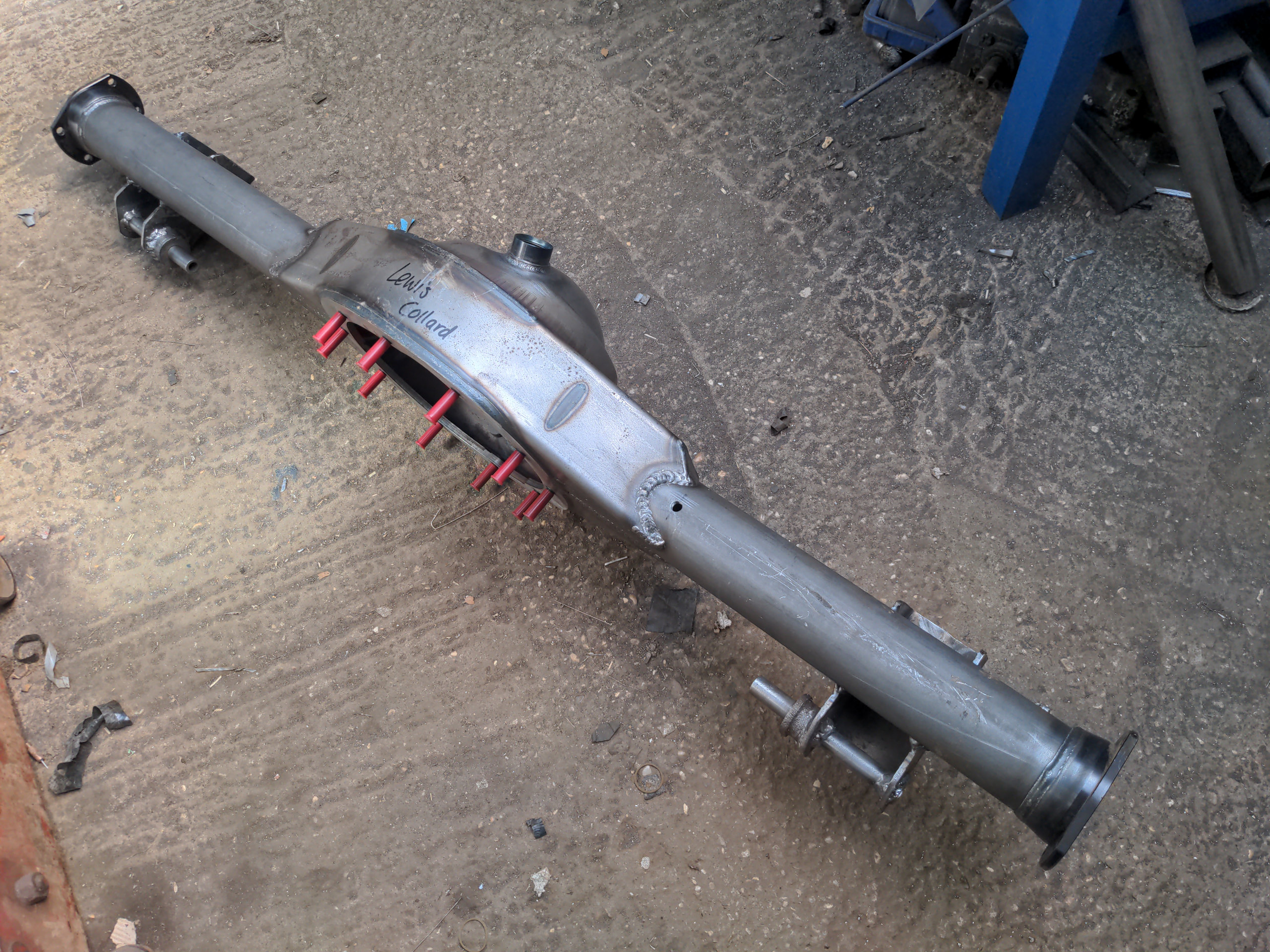
...and you have a Ford 9-inch axle housing with two home-made leaf spring perches for a Rover P5. Cool!
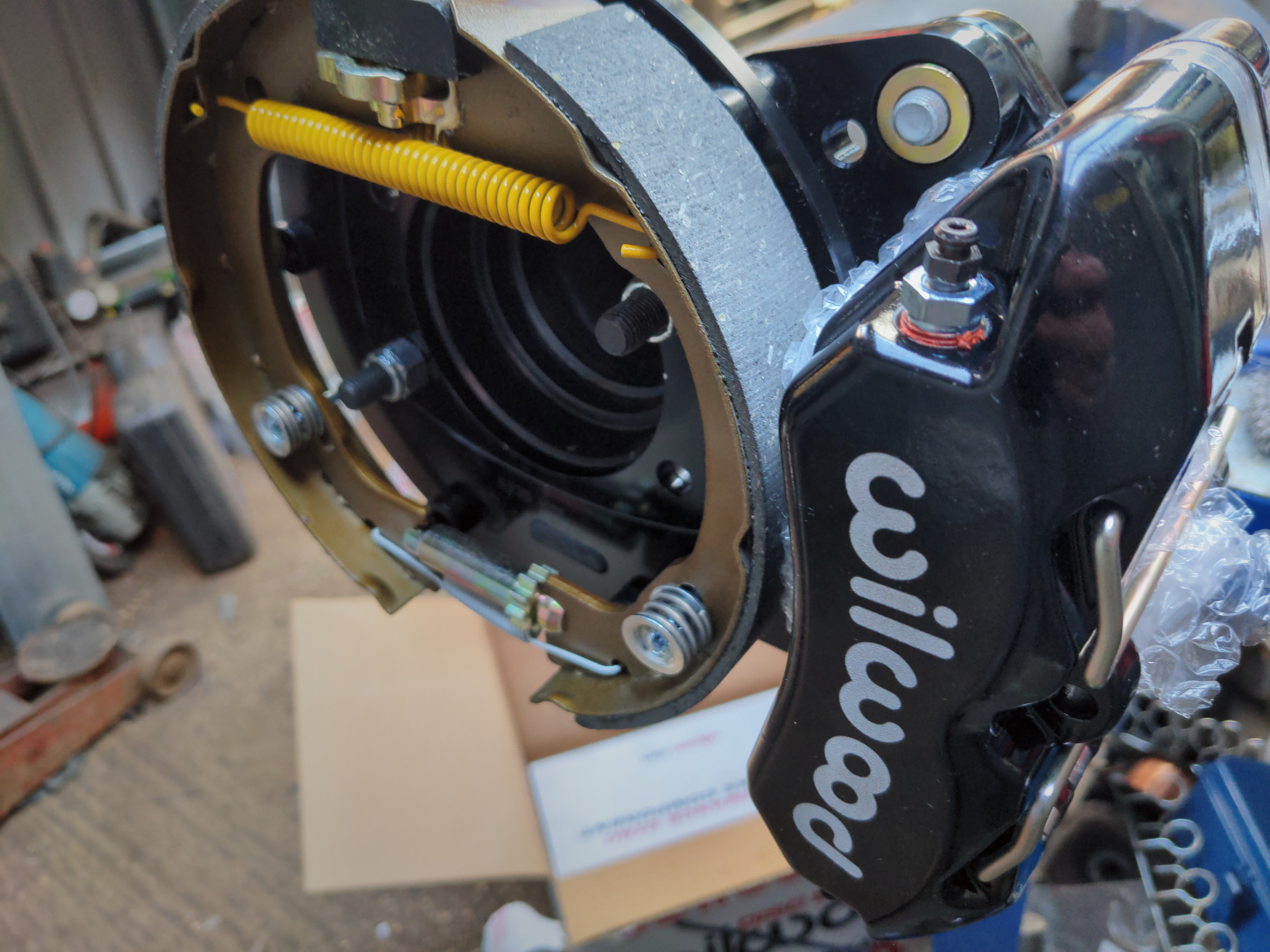
It doesn't have a diff or driveshafts yet. This is already in the works (thanks Hauser!). And it doesn't have any fixtures for routing the brake lines. But to be able to make those I would need some brakes, because otherwise I would just be guessing where those fixtures needed to be. And that's why I called Hauser Racing again, and got talked into buying a box...
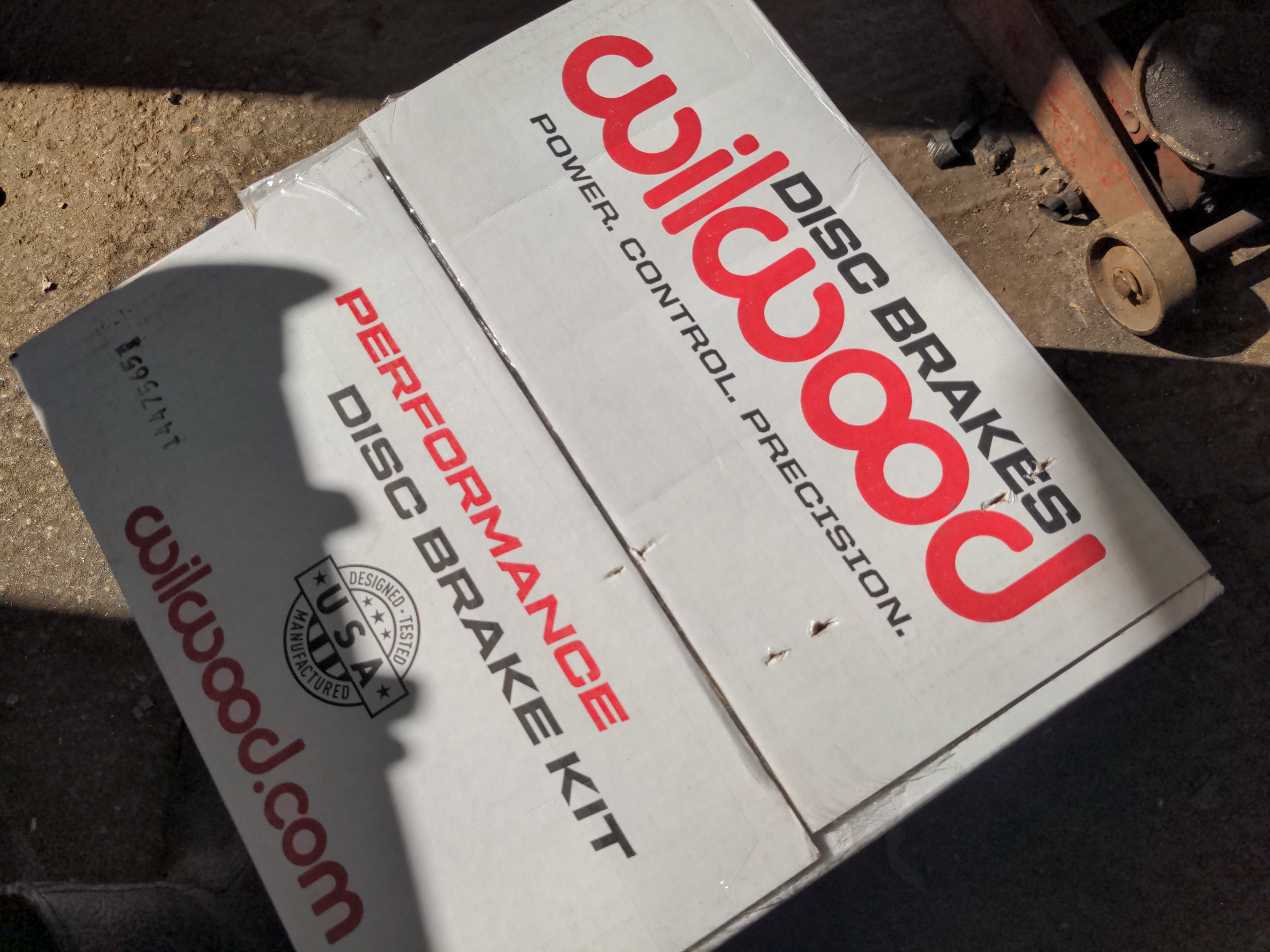
...containing a brake kit for the Ford 9" axle, with 11-inch vented discs and Wilwood four-pot calipers. But I'll tell you about that in part 3.
See you next time.
:)