I put the radiator in the wrong end of a Rover P5
You alright there? Me too. I've been busy.
Previously, I wrote:
and anyway nobody said that the radiator must be at the front of the car.
:)
My thoughts are like wild animals. Sometimes they're exciting, sometimes they're cute, and it's best not to leave two of them in a room with only each other to feed on.
For example, let's look at the boot of a tatty Rover P5.
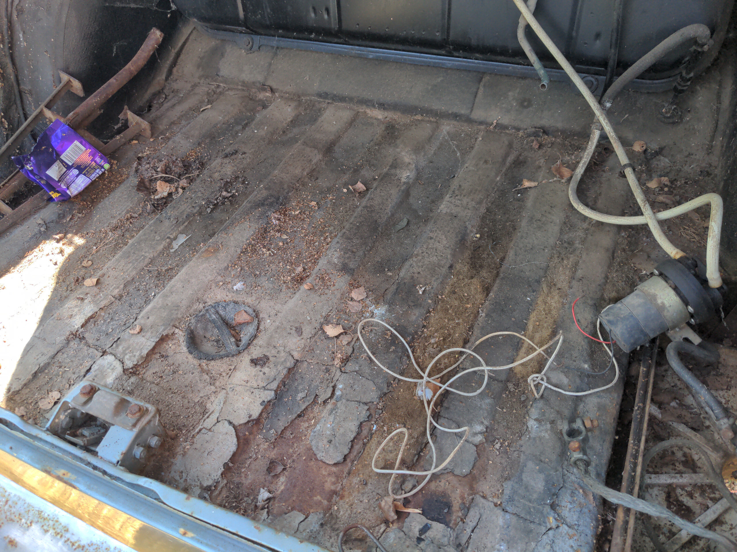
Normal people would say something like "look at the size of that! There's lots of room for suitcases and shopping or whatever the fuck normal people put in their cars". I, on the other hand, thought "look how much room there is for a radiator".
So, let's talk about that. Basically every car with the engine in the front have the radiator in the front of the car too. That means the coolant lines are short and simple, and means that the boot can be used for suitcases and so on.
Alternatively you can put it in the back of the car. Here is a rear-mounted radiator in Matthew Holder's E36 Compact.
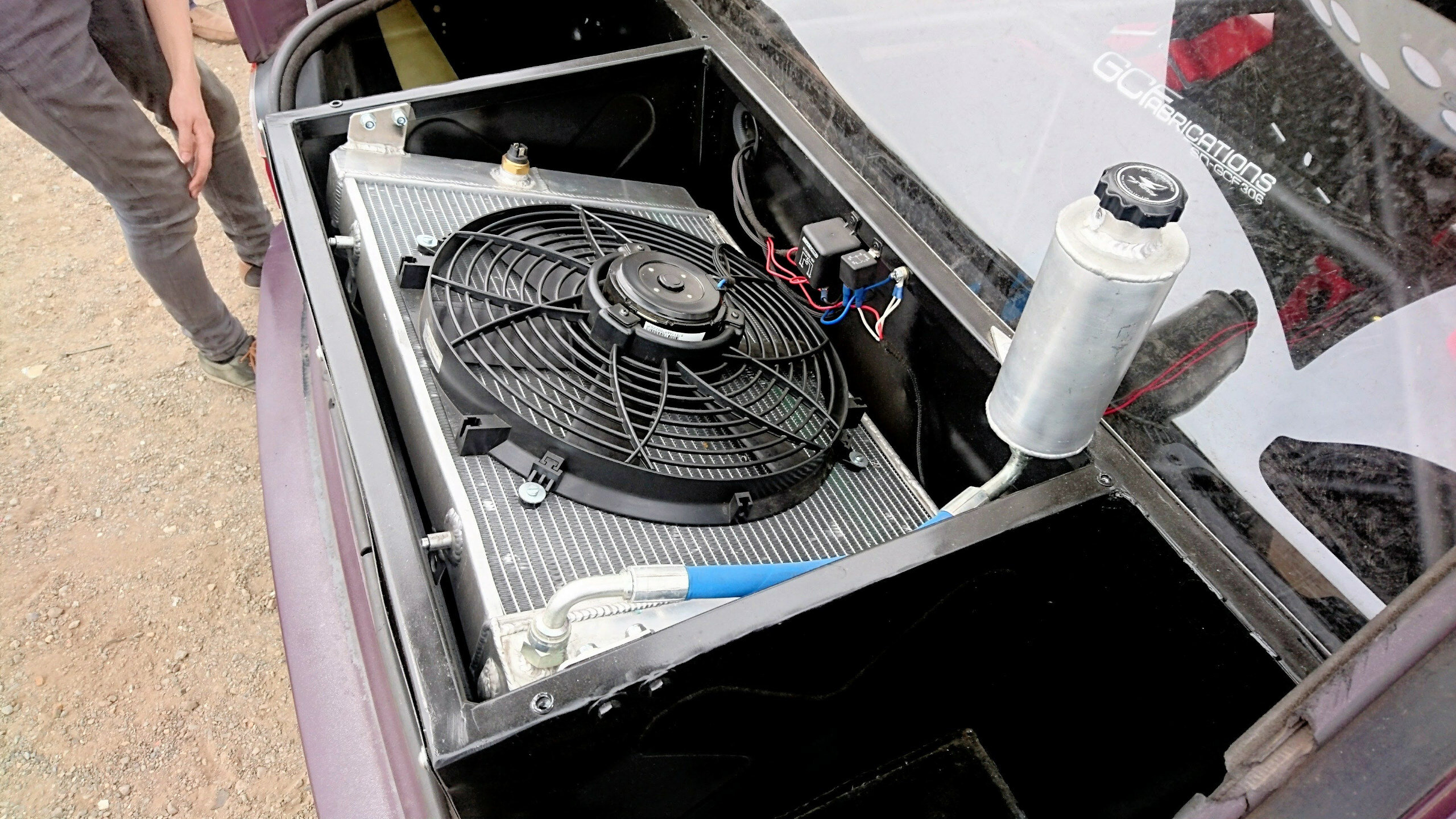
Putting it in the back of the car, i.e. in the boot, has some overwhelming advantages which make it common in torture-test applications like drifting. The primary benefit is moving the primary source of heat (your engine) away from the primary means of removing heat (your radiator). This helps mitigate heat soak, which I'll crudely summarise as "everything getting hot and keeping everything else hot".
There is a smaller benefit that you have much longer coolant lines, and those lines contain coolant, and that adds to the total volume of coolant in the system. A pair of three-metre long coolant lines an inch in diameter will increase coolant capacity by about 3 litres, or roughly a quarter of the capacity of the entire coolant system of the car the engine came out of.
There are disadvantages to this. You lose luggage space; but if I want to move anything I would rather use a practical car. The coolant lines are longer and more complicated. And invariably this means the radiator is no longer the highest point in the cooling system. Some people believe that makes it more difficult to bleed, but this is a solved problem.
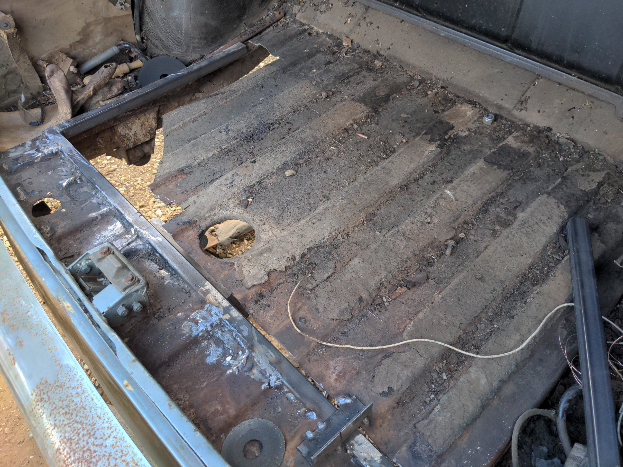
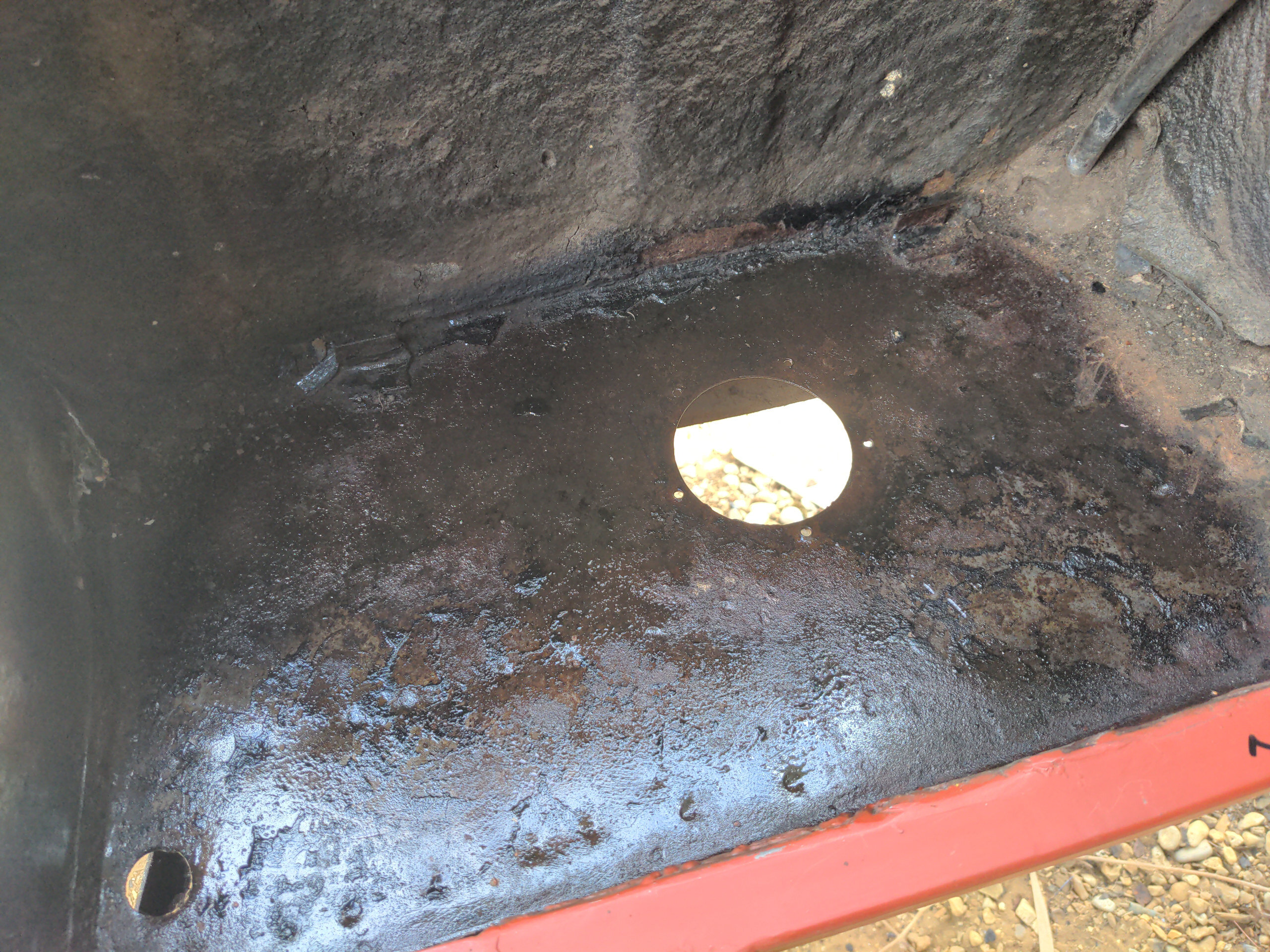
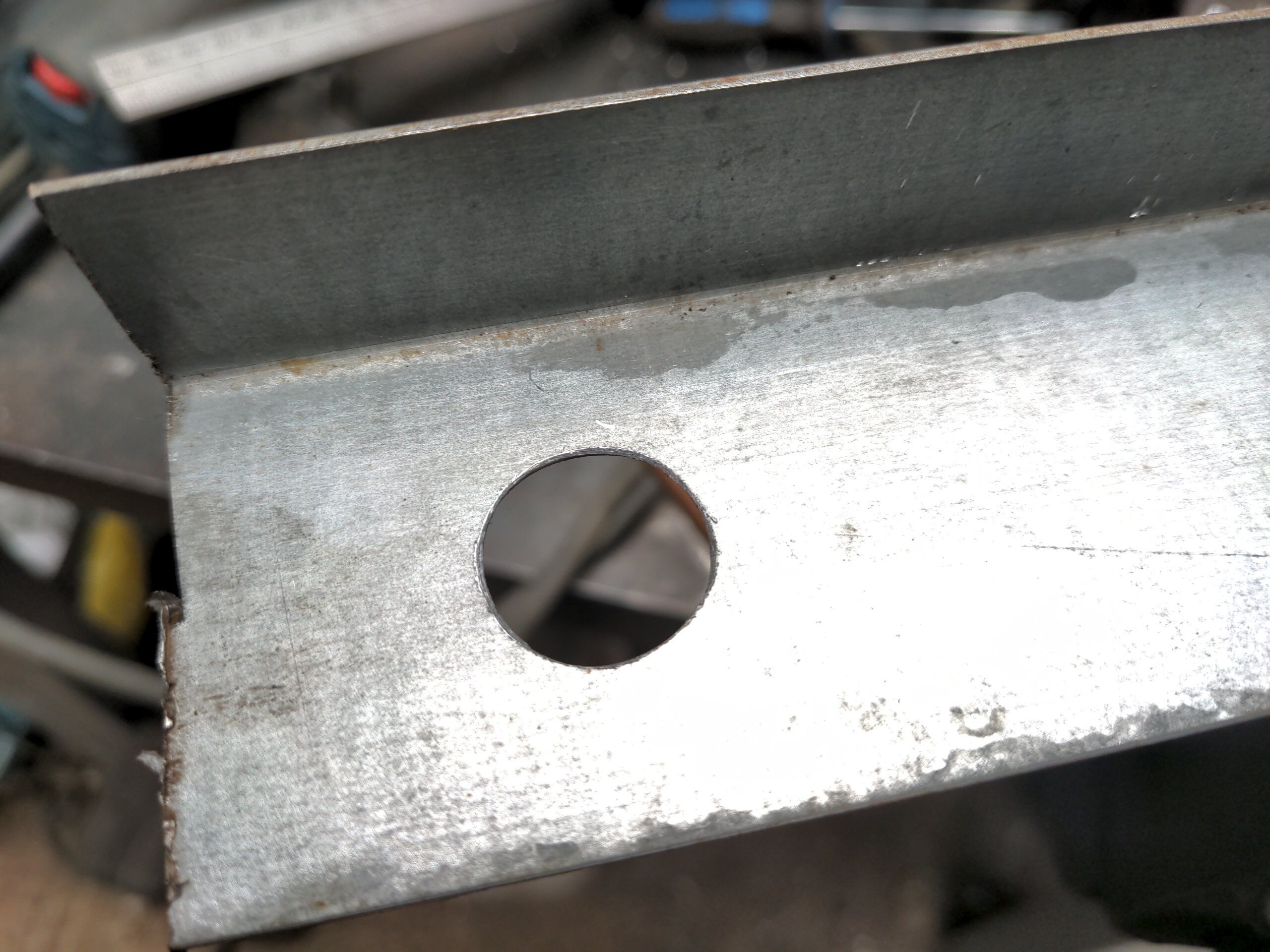
Anyway that's how I ended up cutting out the boot floor of a Rover P5. But before I could cut any of it out, I wanted to remove whatever this stuff was from it.
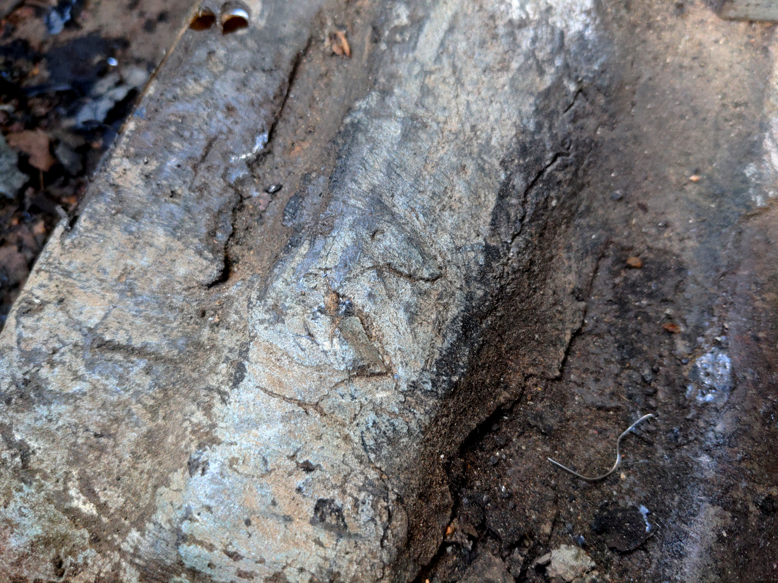
This needed to be removed if I was to weld anything to the remainder of the boot floor once I cut it out, and because I was planning to progressively cut out the floor and reinforce it I would have to remove it before doing any cutting. This stuff also made it hard to mark any cut lines on the floor.
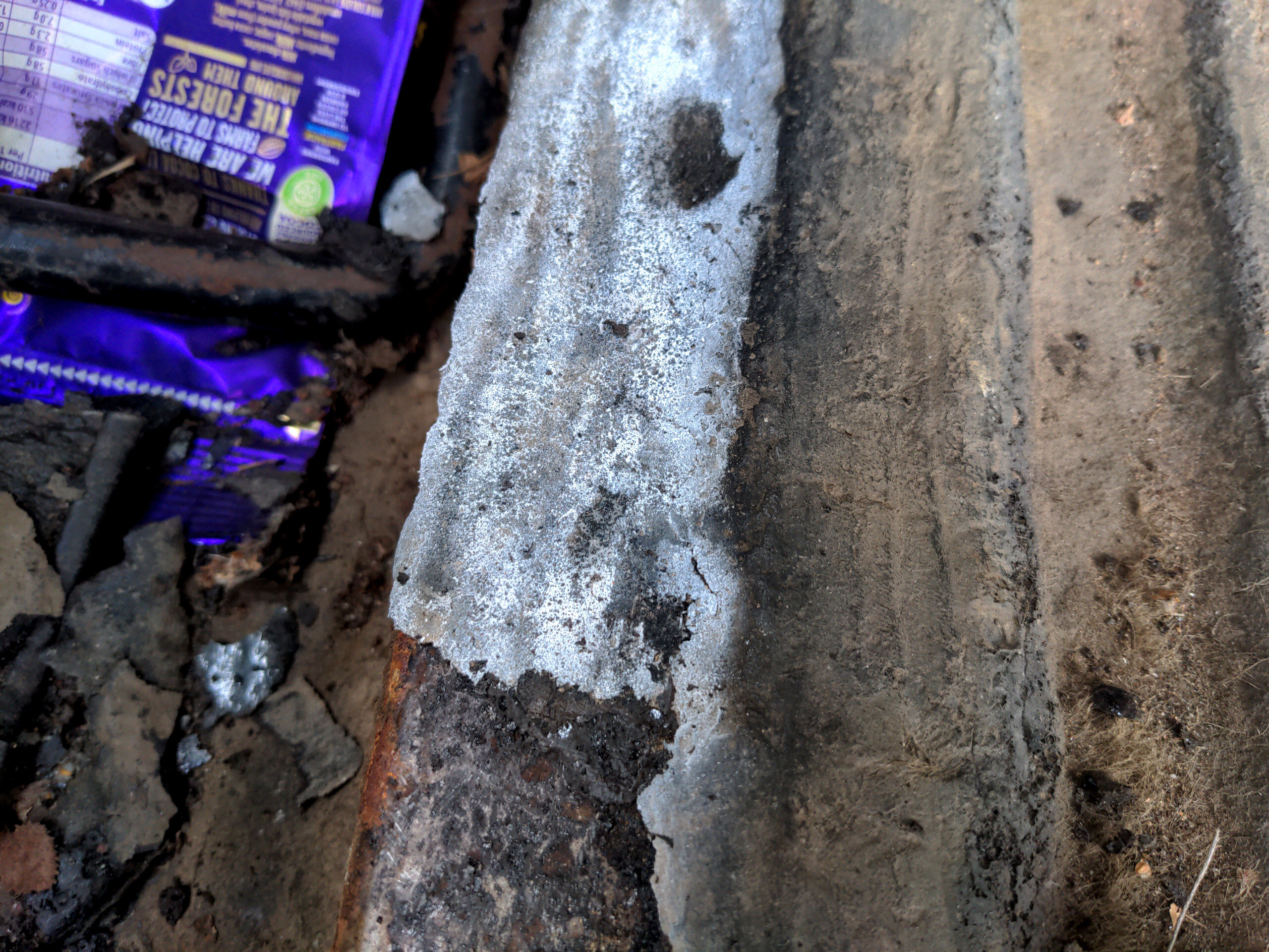
It seemed like bitumen; whatever it is my health is likely not better for having been in its vicinity. It can't be ground off with my usual tools like various drill attachments or angle grinder things, because they just heat it up and spread it around, and give you a differently-shaped mess to remove. You'd never get a surface clean enough to weld to. And manual means like wire brushes and scrapers just seemed to bounce off it.
What helped here was freeze spray, which is apparently used for diagnosing electronics. This makes it brittle for just long enough to remove the bulk of it with a hammer and chisel and by the way this took forever.
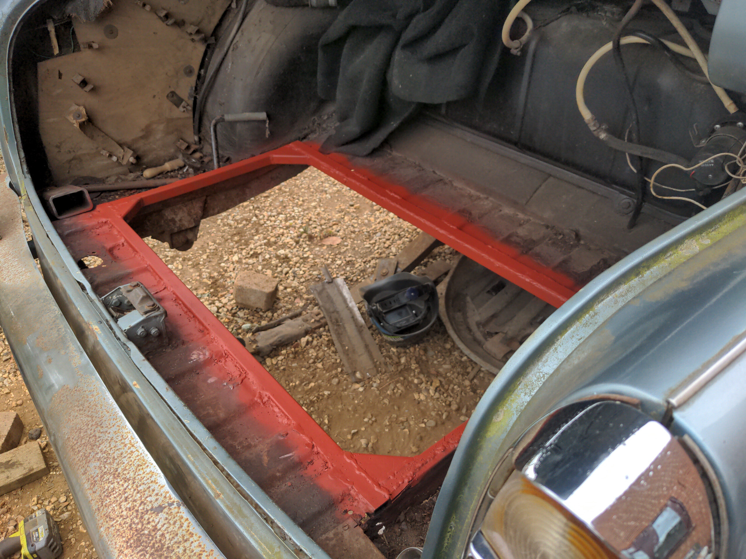
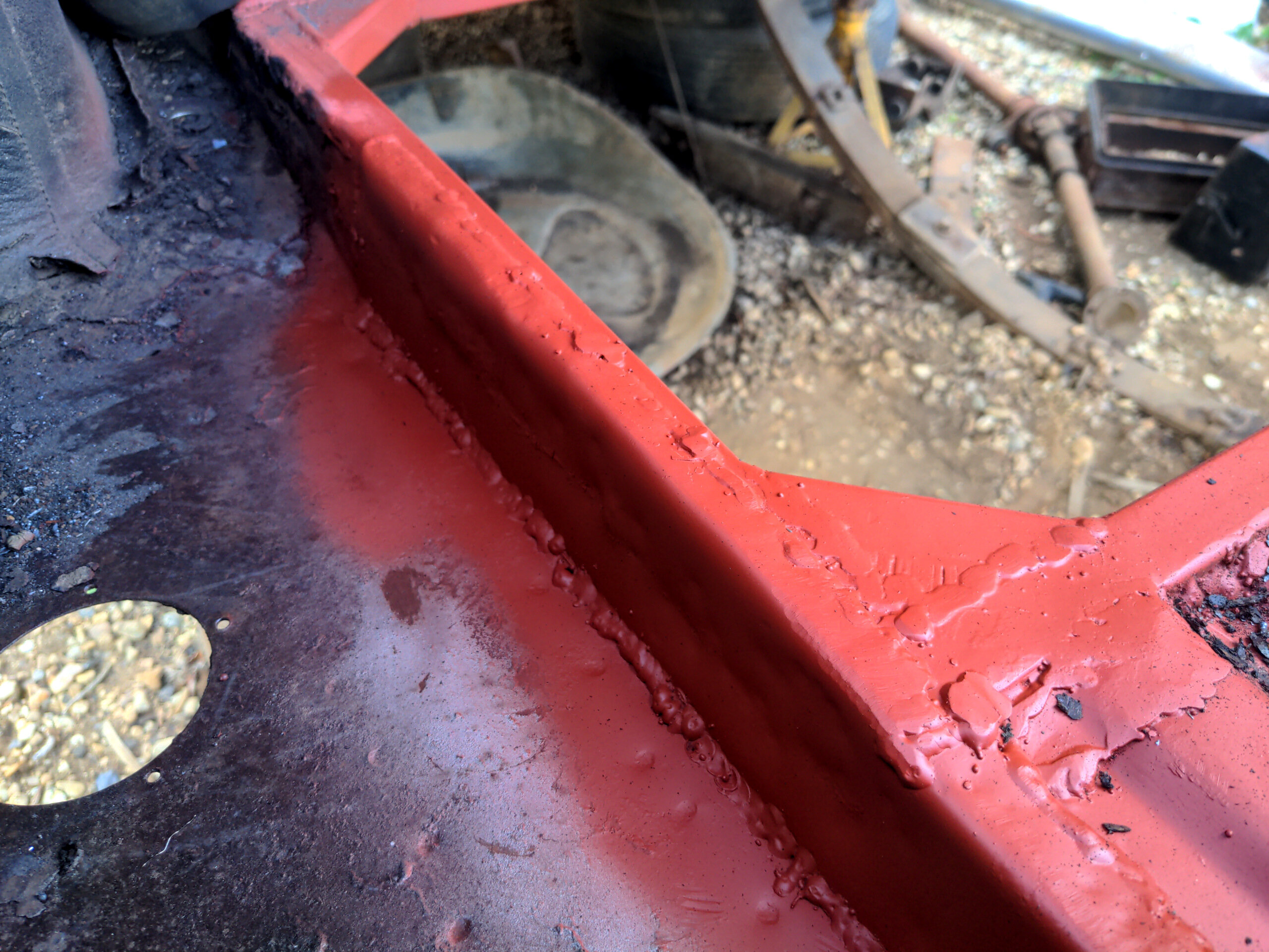
Originally, as said, my plan was to temporarily brace the floor with angle iron joining the edge which I was cutting out, and then replace it progressively with 25x2.5mm steel box section. You can see some of that temporary bracing on the front edge below.
It turned out to not be necessary; my assumption that the boot floor was critically structural was invalidated when I started cutting it out. It was so floppy that I could flex it between two fingers. Still, I decided to continue with the reinforcement. It adds some rear-end rigidity (especially with two-inch gussets), probably doesn't add any weight, gives me somewhere to build the radiator mounts from, and looks better than an unfinished hole.
But while welding that in, I became increasingly aware that I wasn't welding this to very much. That was because the area where the battery box used to be (which is not where the battery is going to be) was, quite predictably, entirely rotten.
That started a side quest...
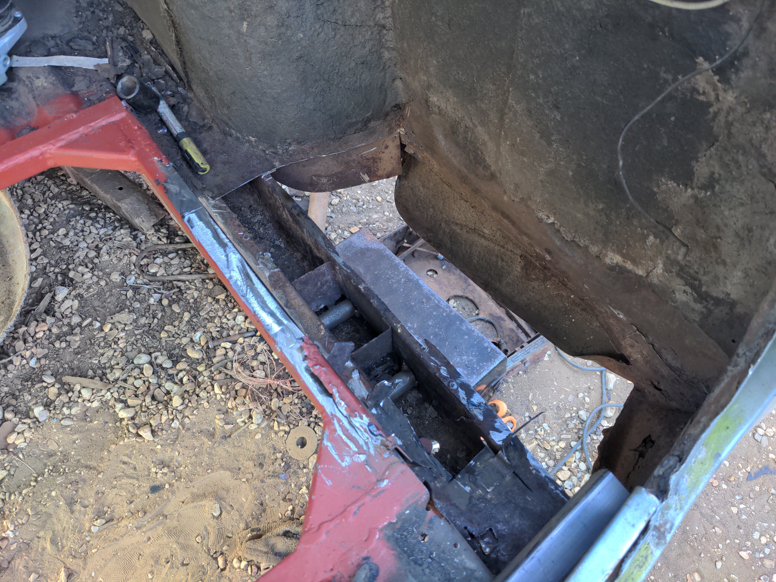
...of replacing about a foot and a half of steel, and there went an entire day.
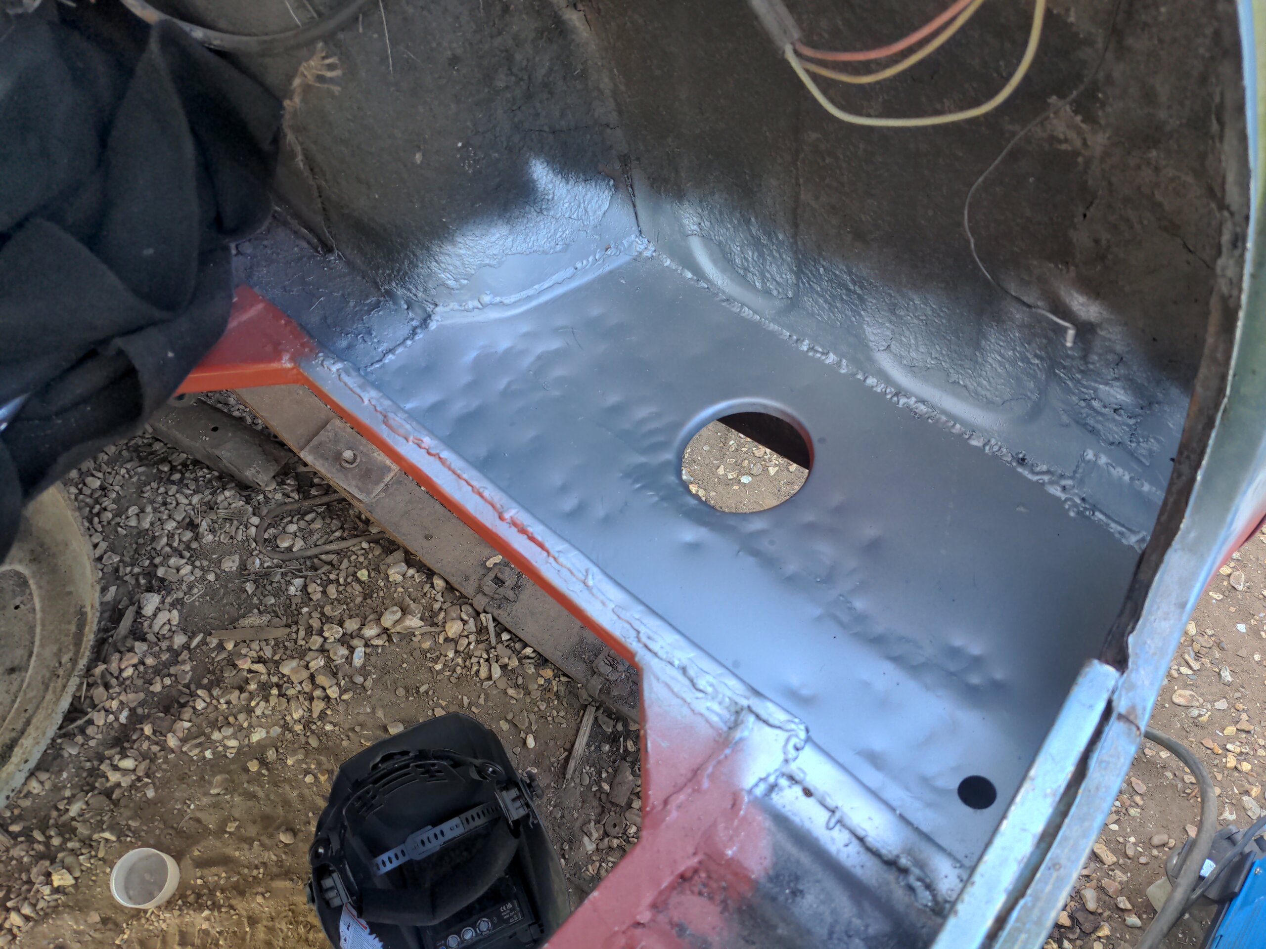
The other side looked pretty grim, but after cleaning up most of it was pretty solid.
It only needed most of the upward return (to which I was welding the reinforcing frame) cutting out and replacing. (To Internet welders: I know. It'll hold.)
Anyway, the point of this wasn't just to make a big gaping hole in the boot of my car. It was to make a big gaping hole to get some kind of under-body airflow to a radiator, and after a quick chat with Chris from Pro Alloy (who previously remade the intercooler for my 323 GTX) the radiator I chose was this:
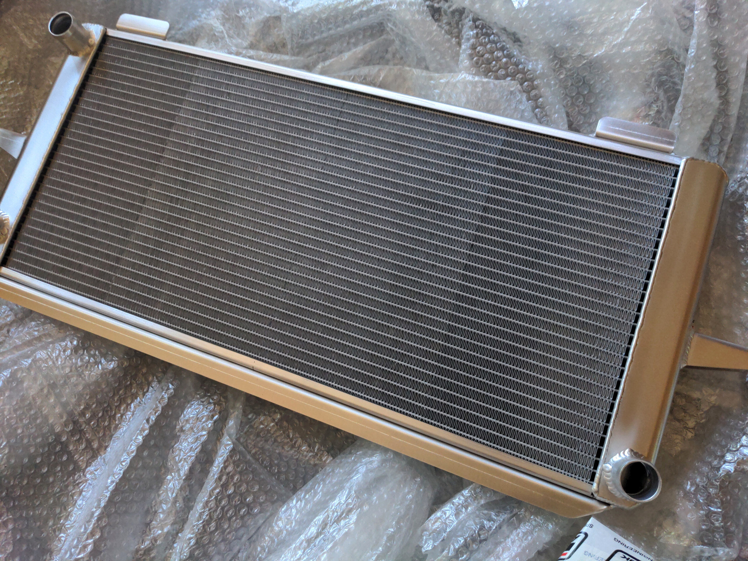
It's Pro Alloy's radiator for the Ford Sierra Cosworth. Any radiator I bought would only be a starting point (I'll want to modify the inlets and outlets); this one was priced well enough and I know it'll be up to the job.
What I could do here is use the original mounts for the Cosworth radiator. There are two of them, and they look like these ones from Burton.
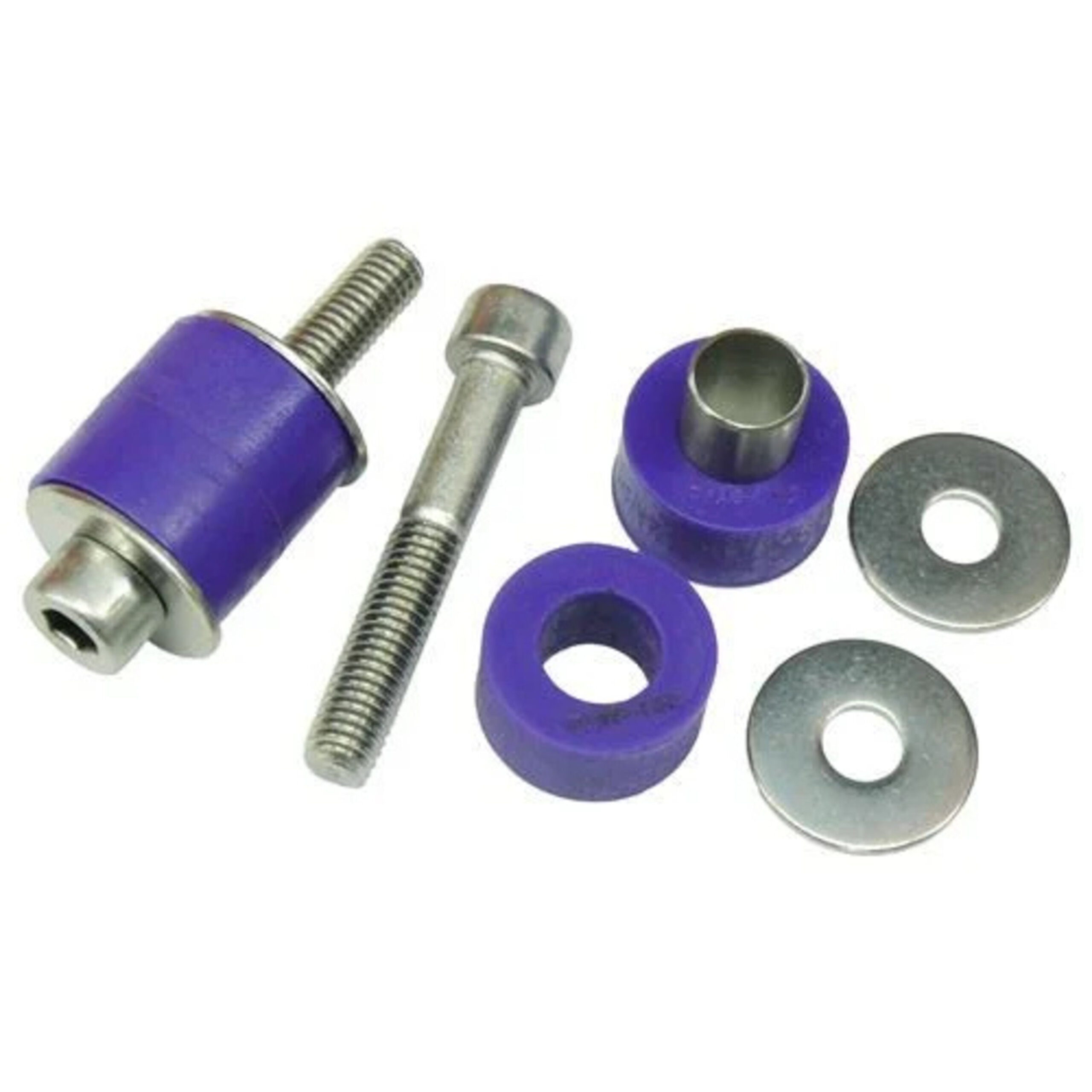
In fact I did buy two of these, and they made it into the final product, because the mounting points existed on the radiator and I might as well use them. But I do not trust them to support the radiator alone in this application. This is partly because they were never designed to support the radiator at a 45 degree angle, which is how it will be mounted in the P5.
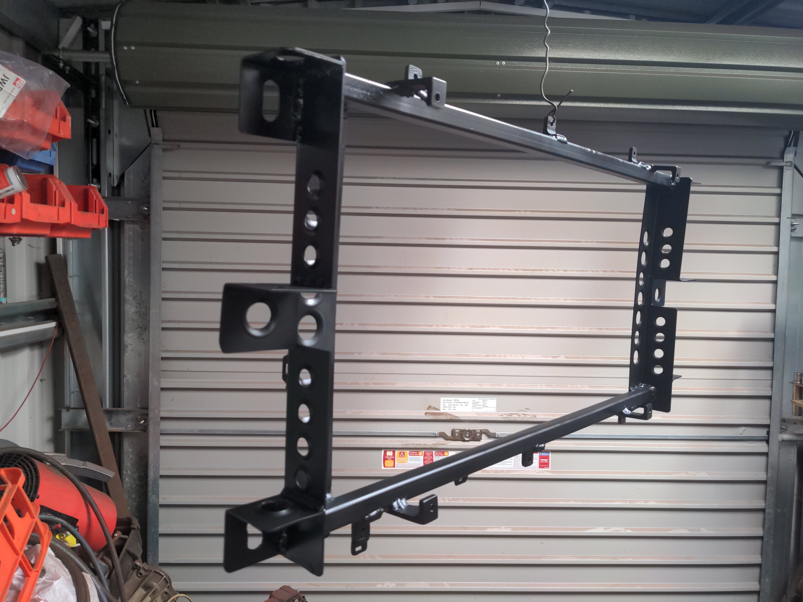
Instead, I needed to make a mounting frame for the radiator, and let's talk about dimple dies.
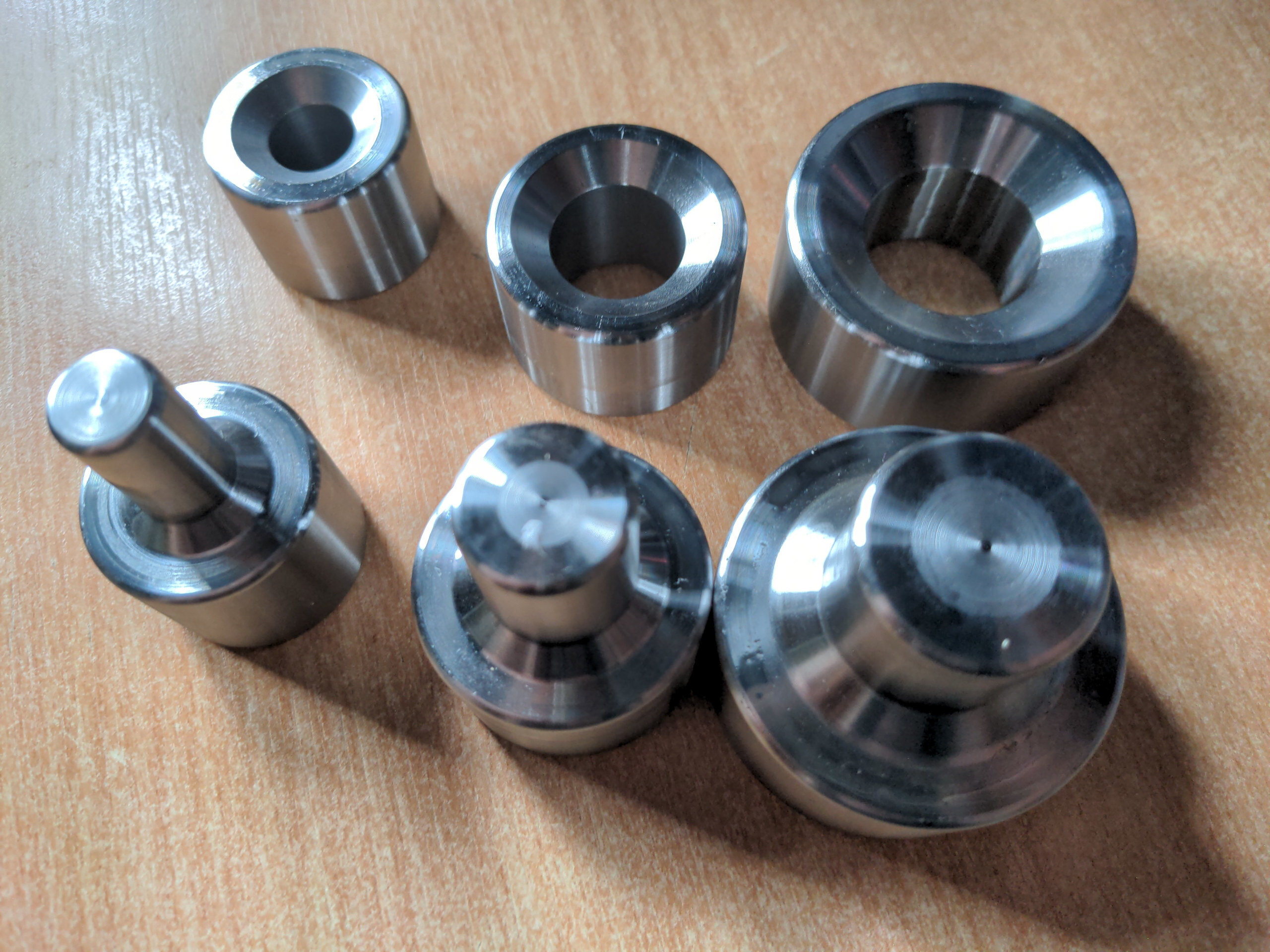
Dimple dies are cool! I don't know why I waited this long to get some! You take a boring piece of steel, drill a hole in it...
...stick a dimple die through it, apply about 5-10 tons of force in a hydraulic press, and...
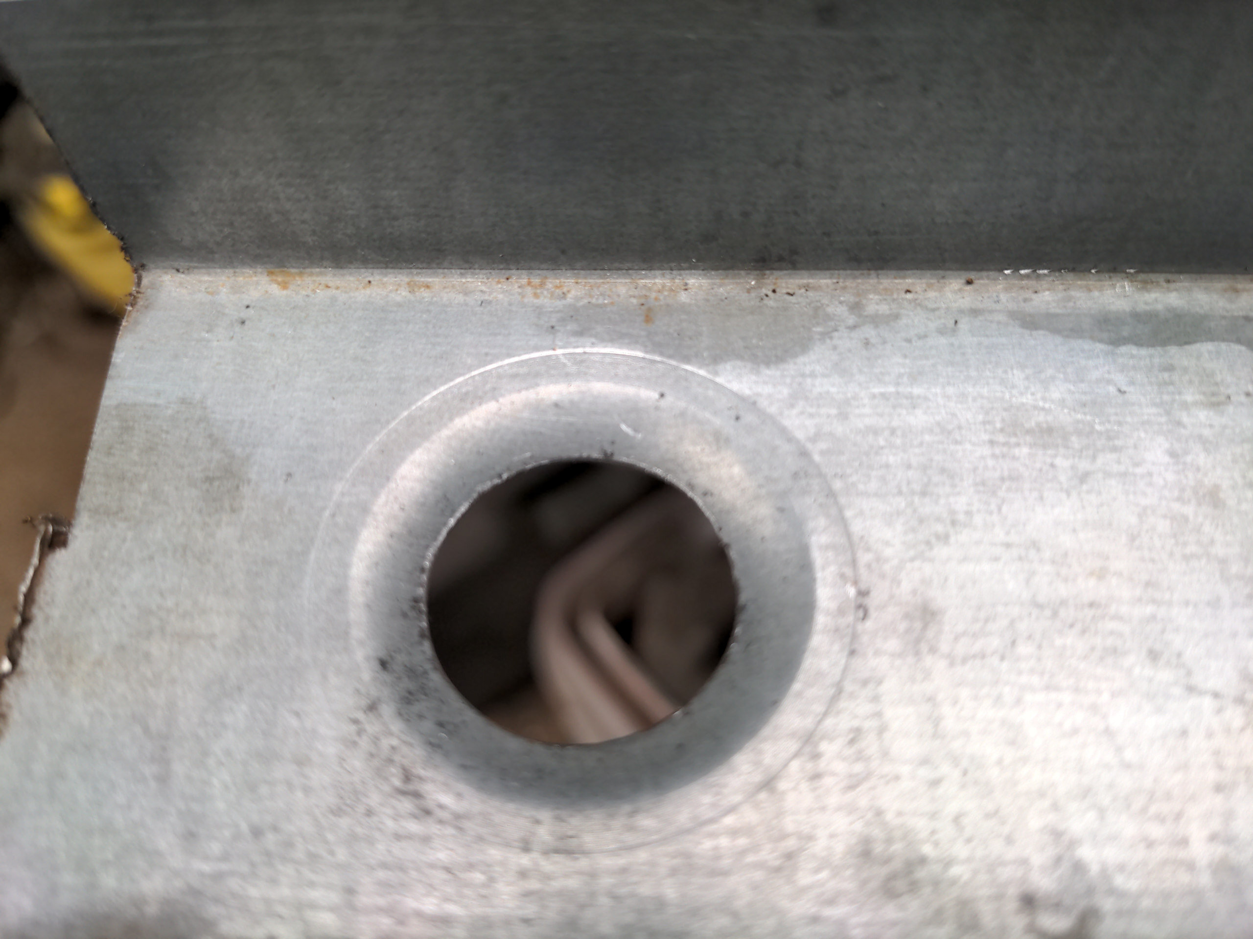
...you are now RACE CAR FABRICATOR. It looks cool, and because a hole with no metal is lighter than metal it saves weight, without compromising strength.
And then if you're me you absolutely go to town on it.
So the frame is made of some 50mmx50mmx2mm steel angle on the sides, with some 20mm box section steel on the top and bottom joining them.
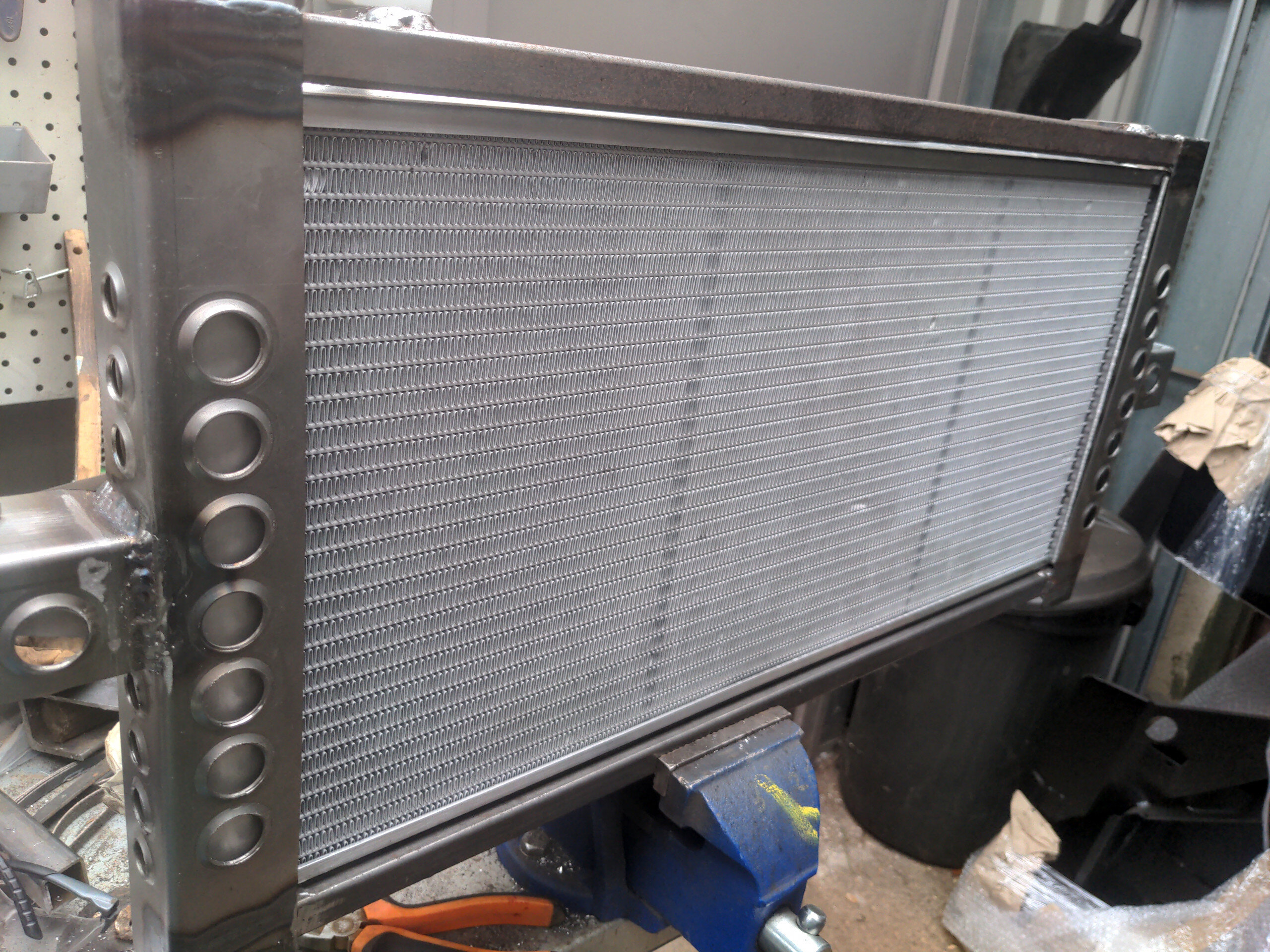
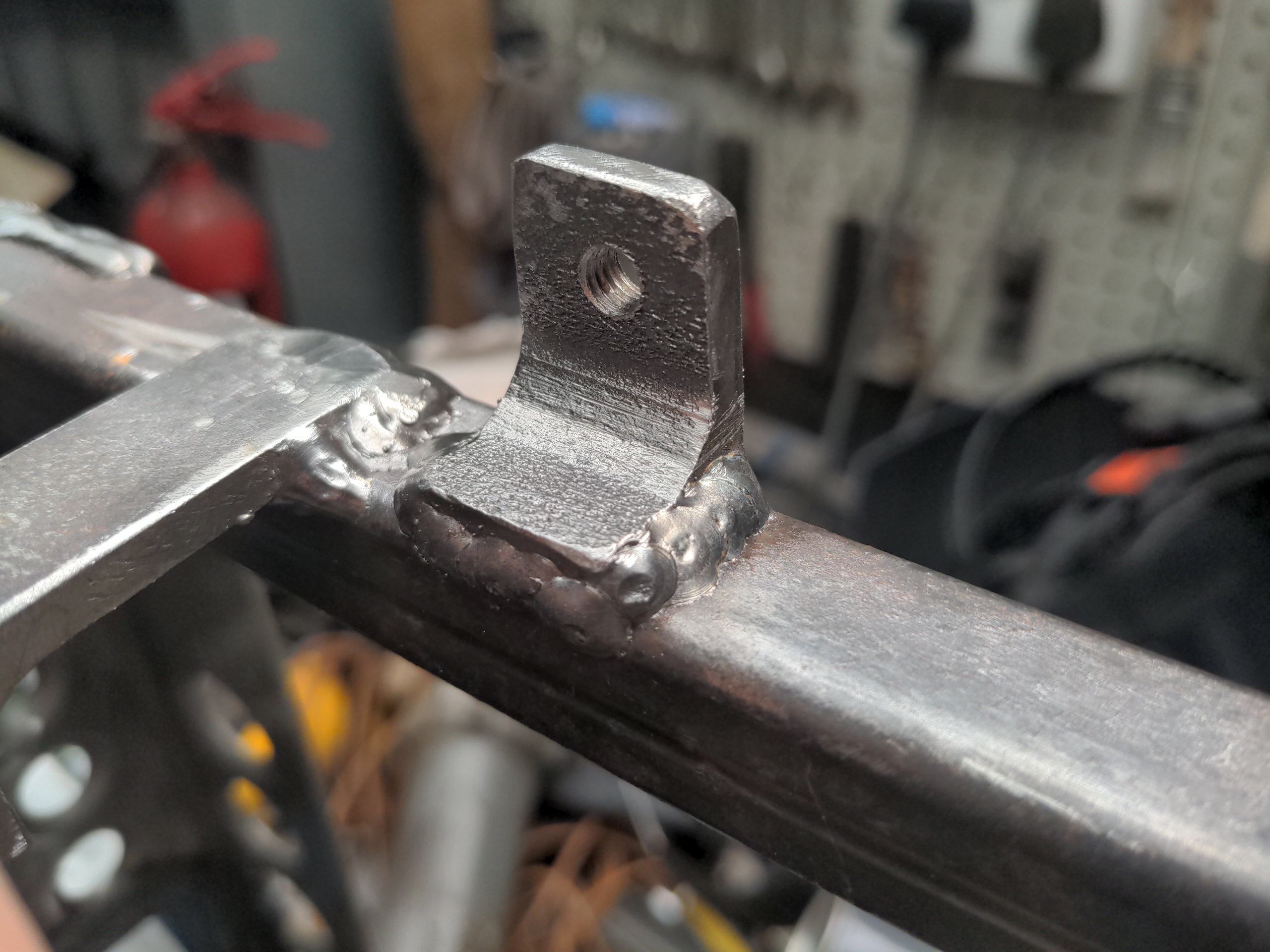
Attaching to that are various threaded mounting points for the radiator itself (using the top and bottom flanges on the radiator) and for a fan shroud. These were made from offcuts of the same massive thick angle iron I used to brace my axle housing when I was welding stuff to it.
And on each corner is a square section of the same 50mm steel angle with a slotted hole for some generic rubber anti-vibration mounting bushes.
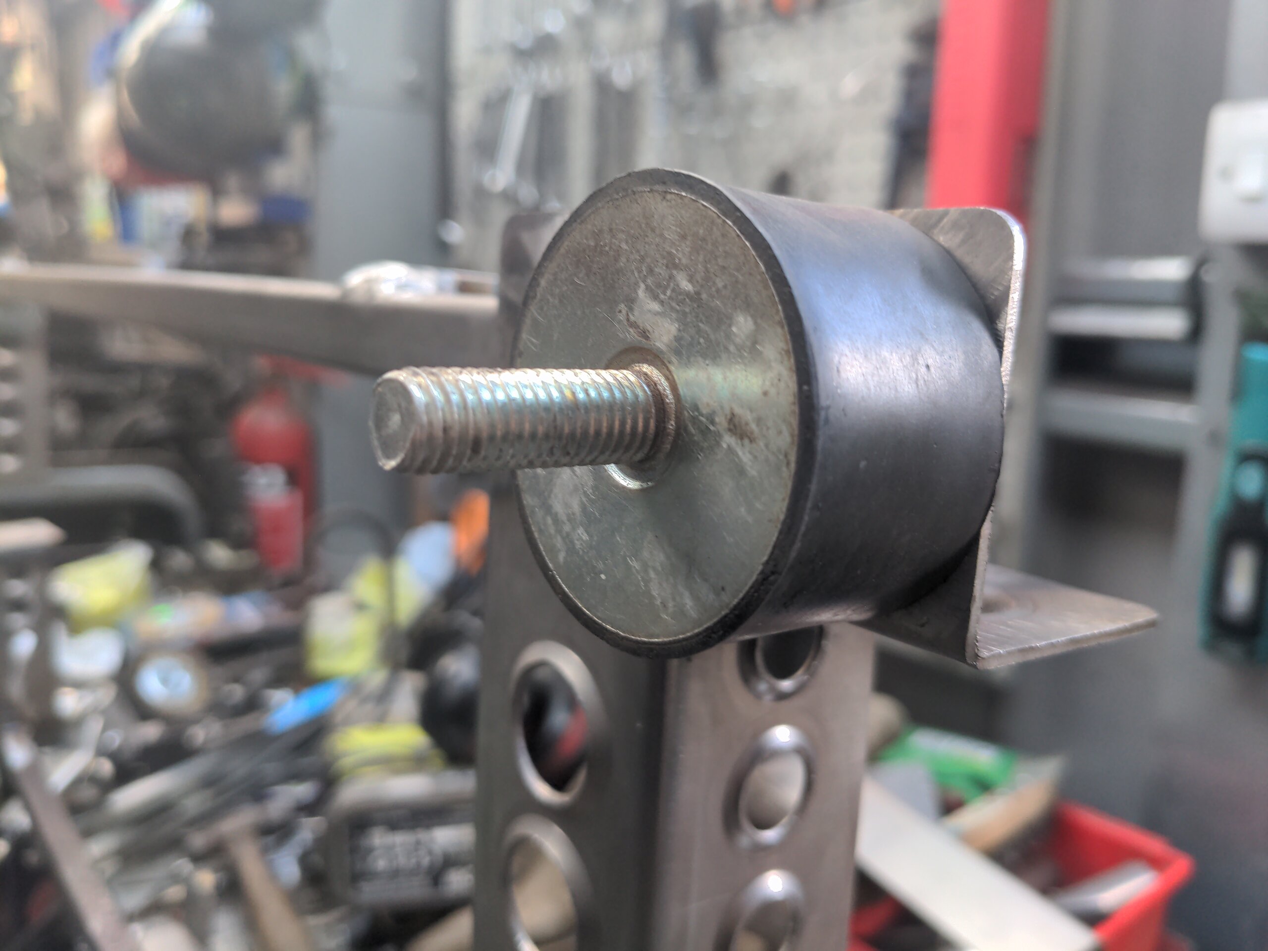
This is critical! It doesn't just isolate vibration; it stops the assembly becoming a stressed member when the bodyshell flexes. If it wasn't flexibly mounted I'd have to make the frame out of much heavier material to stop the radiator becoming stressed and cracking.
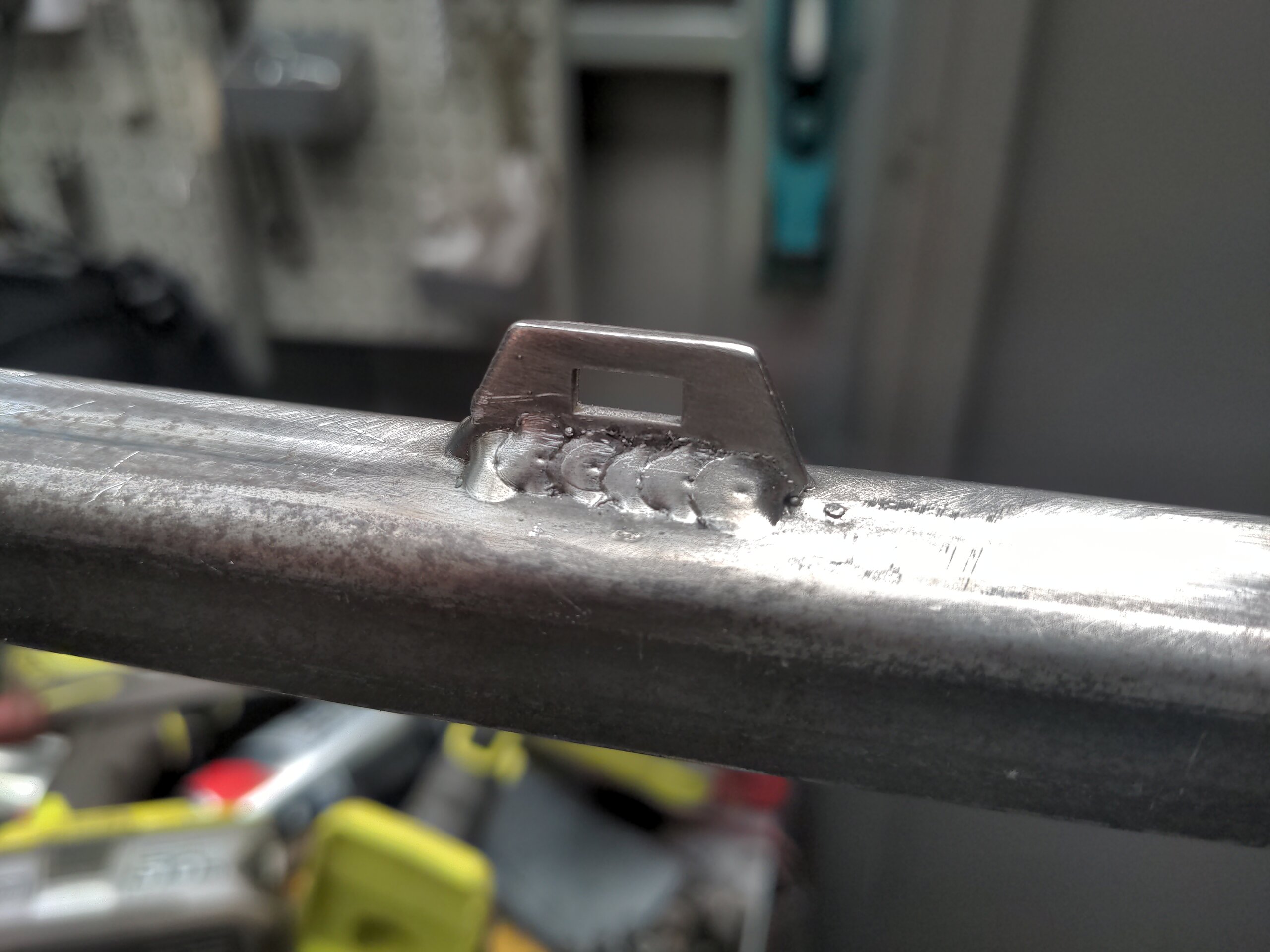
Scattered around are some of these cute little weld-on tabs for cable-tying a wiring harness to. I think I know how my wiring will be routed, so I committed to it.
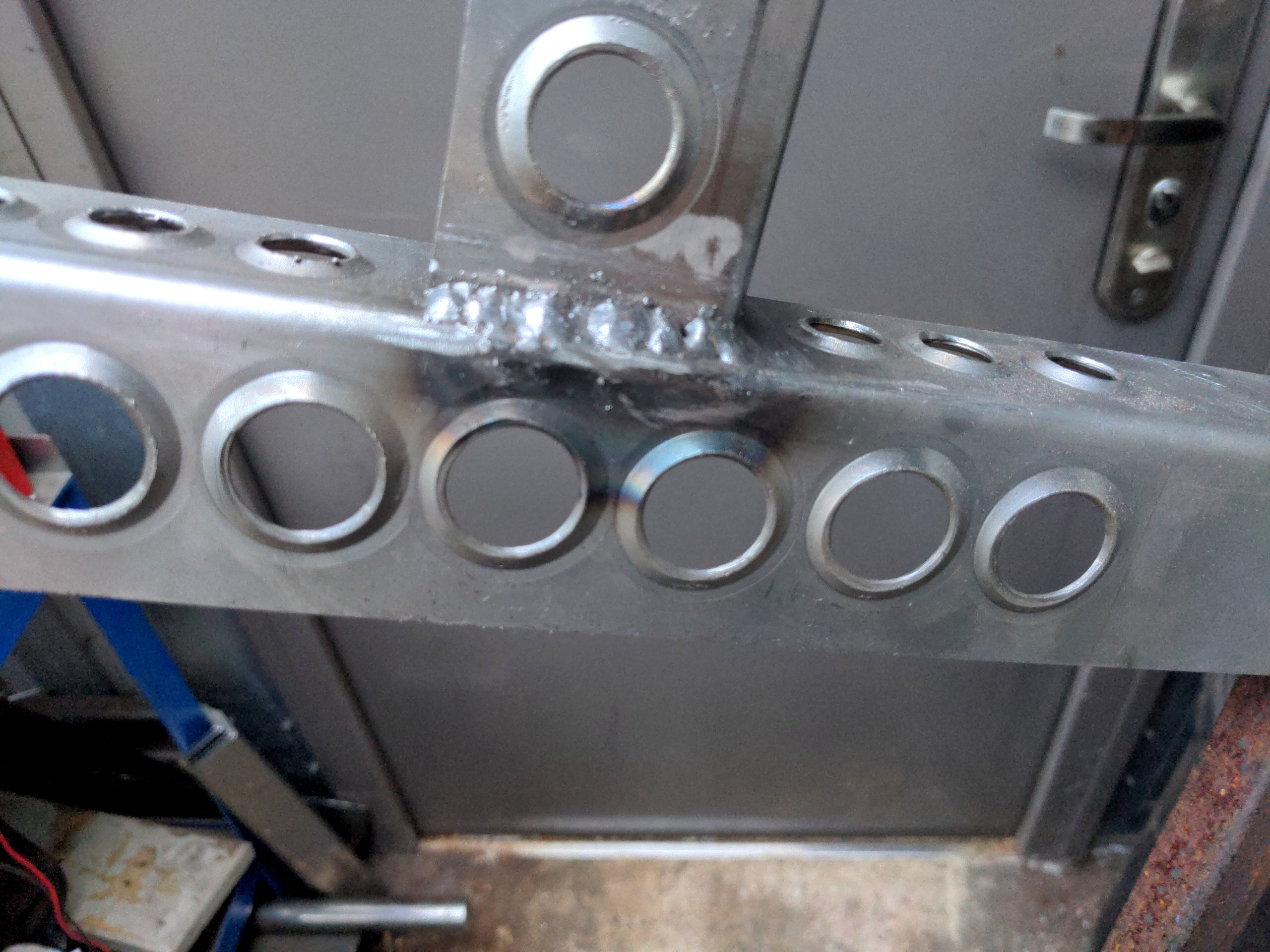
This radiator-holding frame mounts to the body via these brackets which are to be welded on to the frame in my boot. It's made of the same 50mm angle iron used earlier, and the remnants of the 1" box section I used to line the hole I made in my boot floor. The box section is rotated through 45 degrees to impart the same tilt on the radiator when it is mounted.
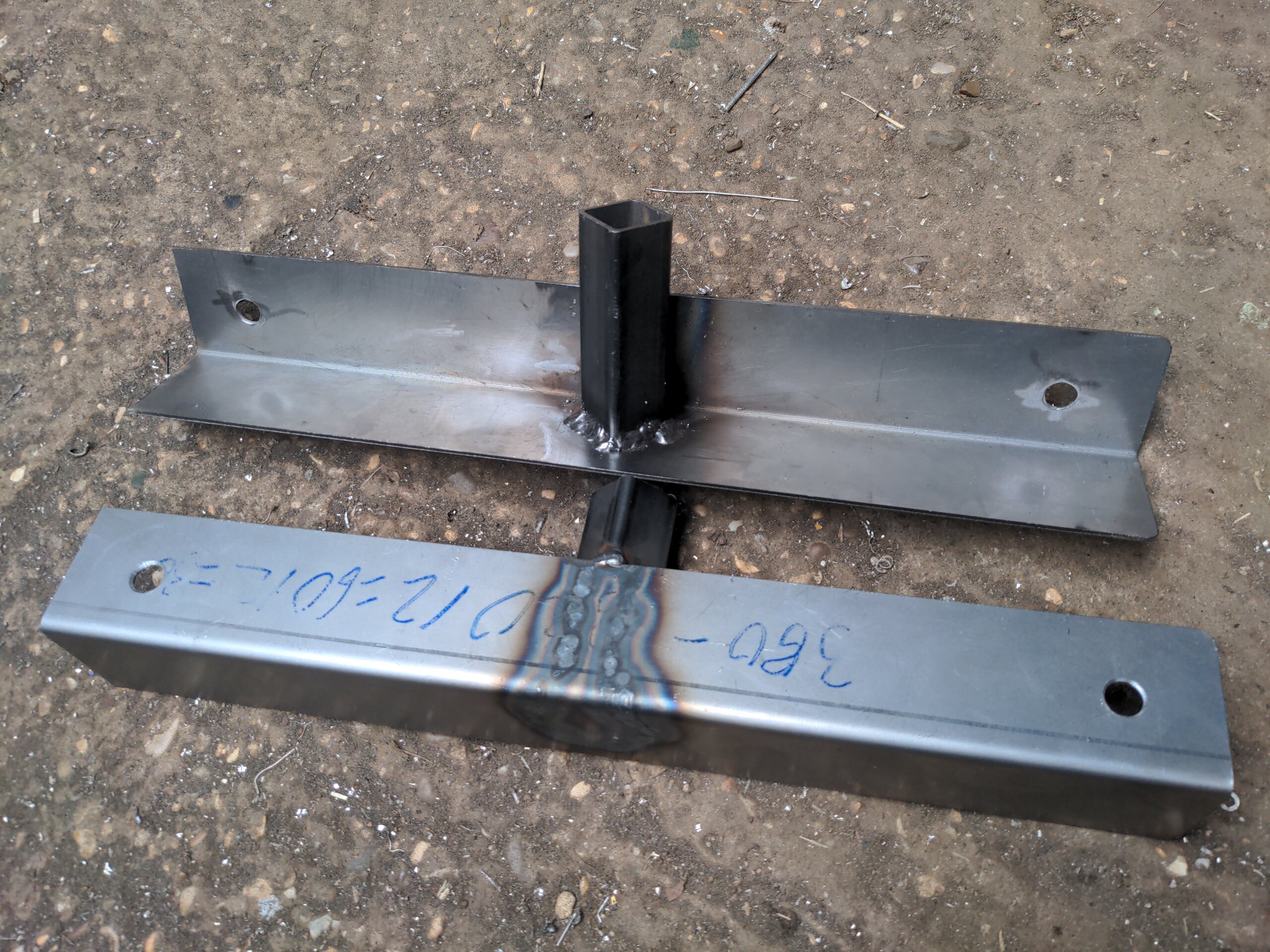
Except that's boring, so let's have some more dimple dies, because race car.
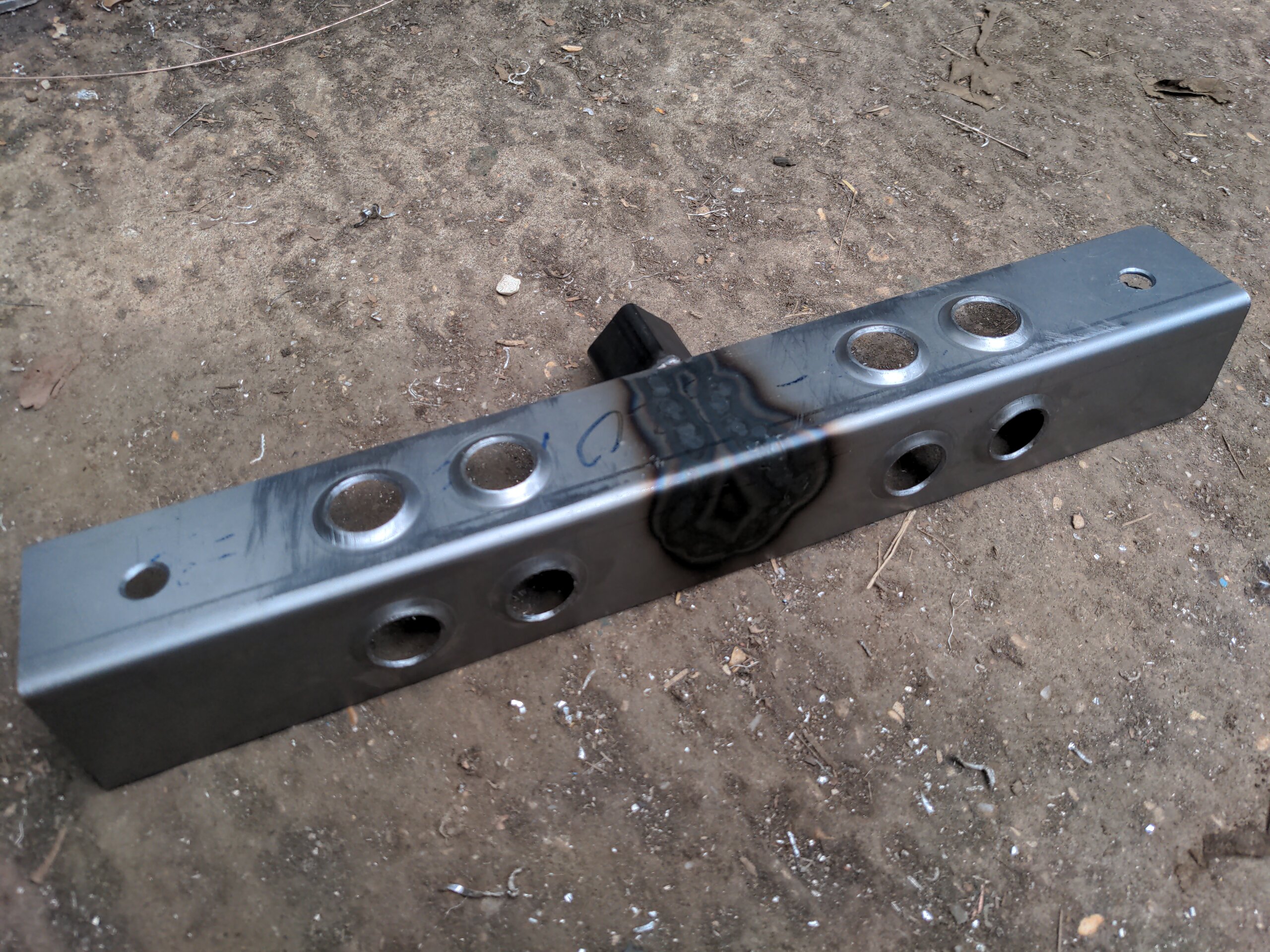
Better!
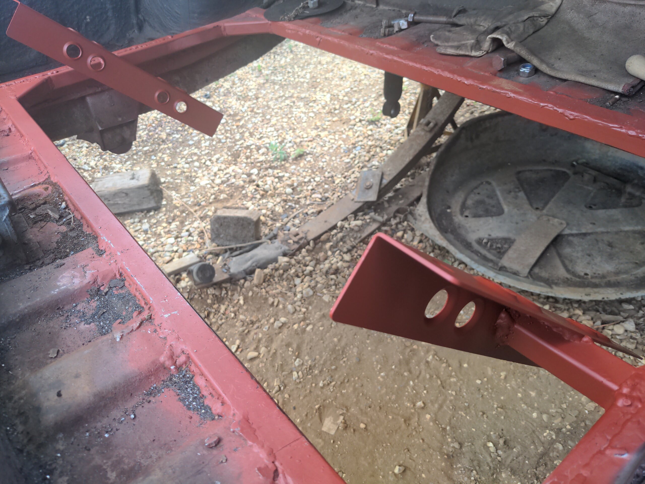
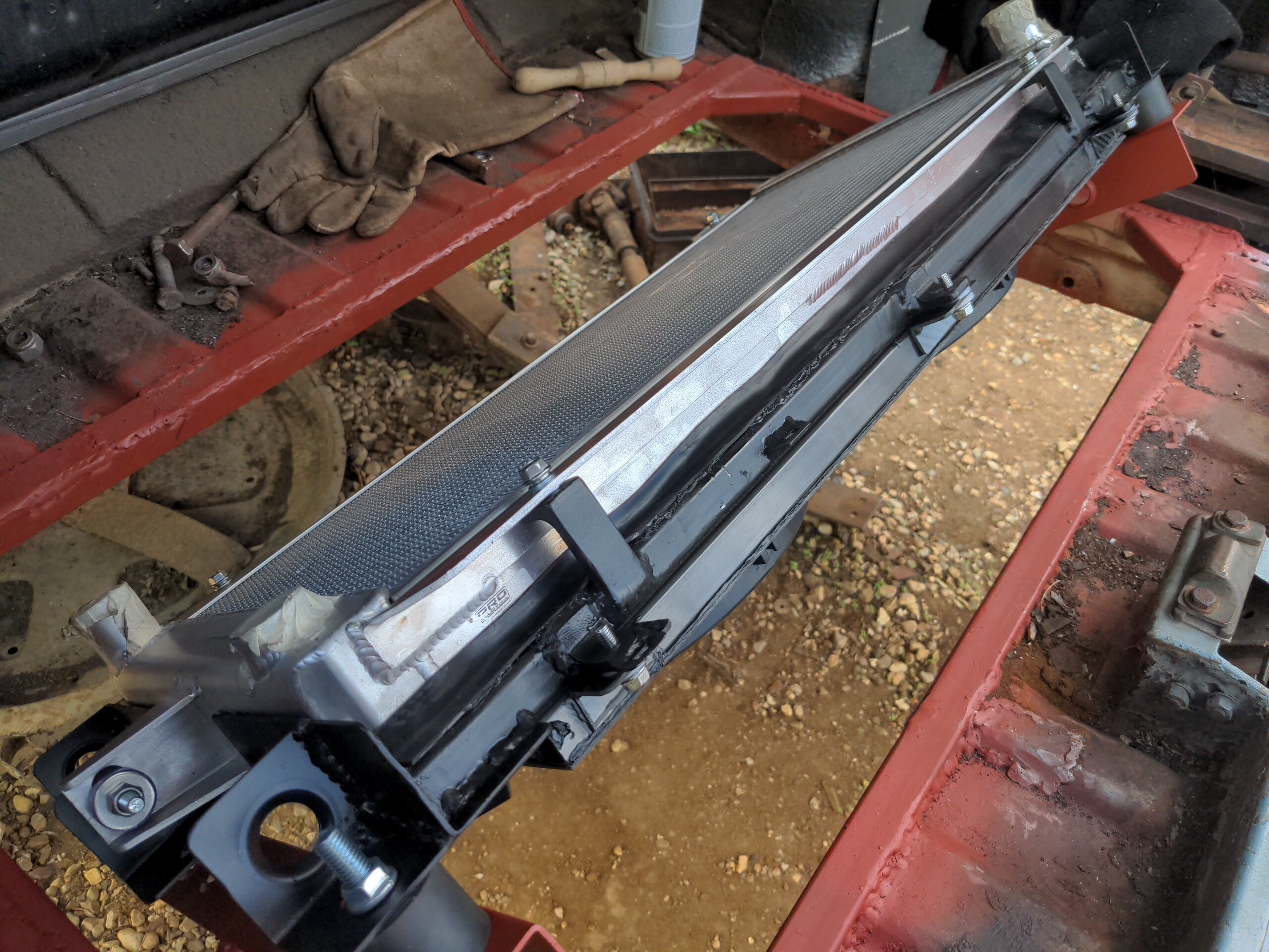
With those welded into the boot I could do the first all-up test.
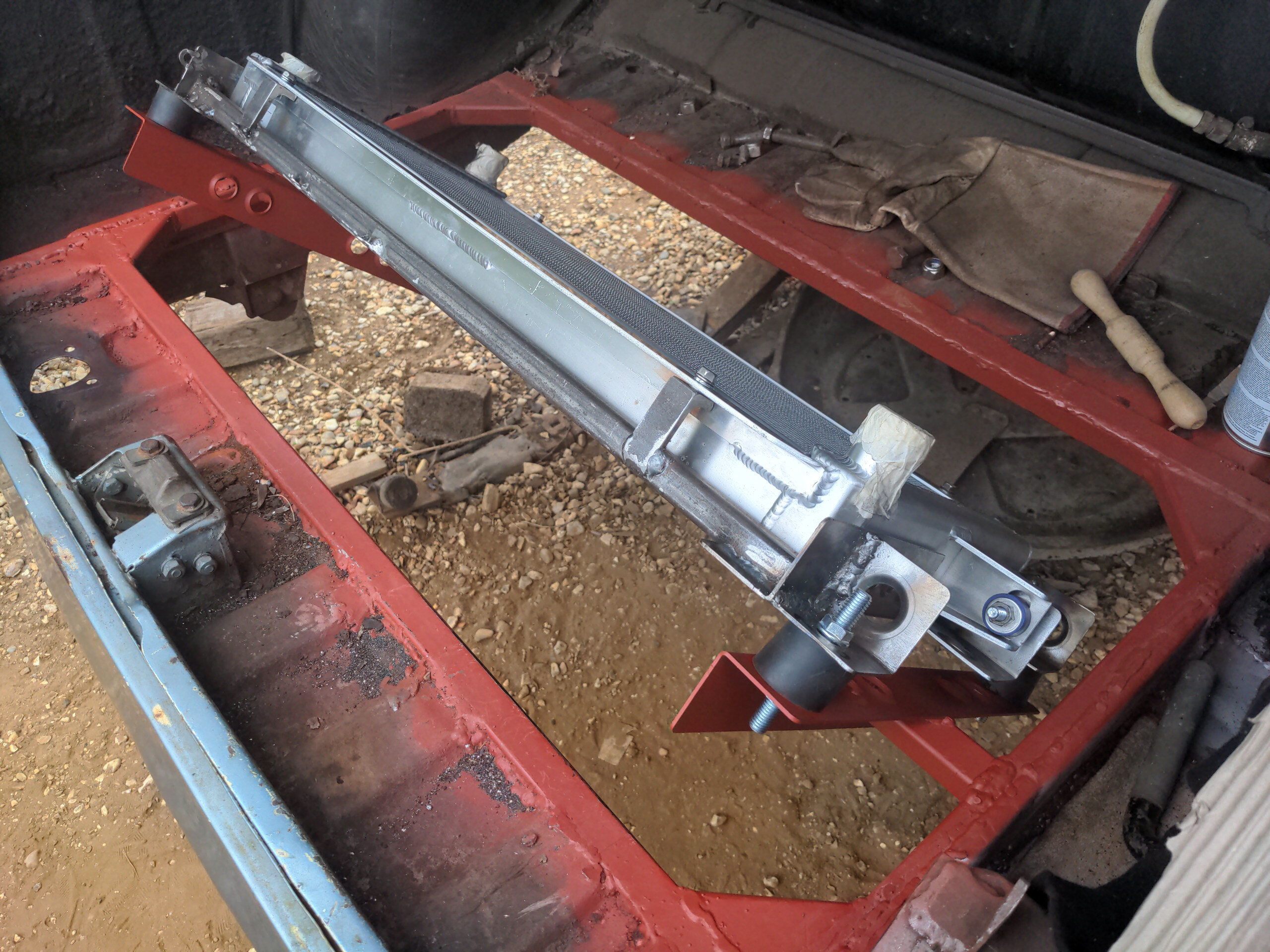
Everything landed more or less where I thought it would! Especially the outlet on the bottom; this ended up just below the boot floor, which is exactly where I wanted them. The mounting rubber closest to the camera was a little over-stressed in the shear direction; I remedied that by grinding the slot wider and welding in a little shim.
Those who know Sierra Cosworth radiators (this is pretty niche) will notice that the radiator is actually mounted upside down. On a Cosworth, the fan switch (which might get replaced with a temperature sensor) is installed on the inlet (hot) side of the radiator. On mine, the radiator is flipped so that the fan switch is mounted on the outlet side of the radiator. This is because I, one guy on the Internet, disagree with Cosworth, engineering geniuses. I don't care what temperature my water is going in to the radiator. It might come out a different temperature to what it went in, e.g. if the radiator is doing what a radiator does, and that temperature should dictate whether the fans need to be switched on or nmot.
At this point the mounting frame just looks like random bits of steel crudely stuck together by some idiot with a MIG, because it is. But with all the welds tidied up and a coat of Jenolite satin black it looked way better than random bits of steel stuck together by an idiot with a MIG has any right to look.
This is all to be cooled by twin 10 inch fans from American Cooling Systems, each of which is allegedly rated for 2187 CFM. That's a lot of fan, but to make it more efficient it is best to have them mounted via a fan shroud so that they pull air through the entire radiator. I mentioned in passing earlier that I was going to fit one. Unfortunately, I couldn't find anyone who makes a fan shroud for Rover P5s with rear-mounted Sierra Cosworth radiators. Strange! You'd have thought that'd be an off-the-shelf part!
That meant I had to make one, and because I was going to make one I thought I'd make one a little bit special.
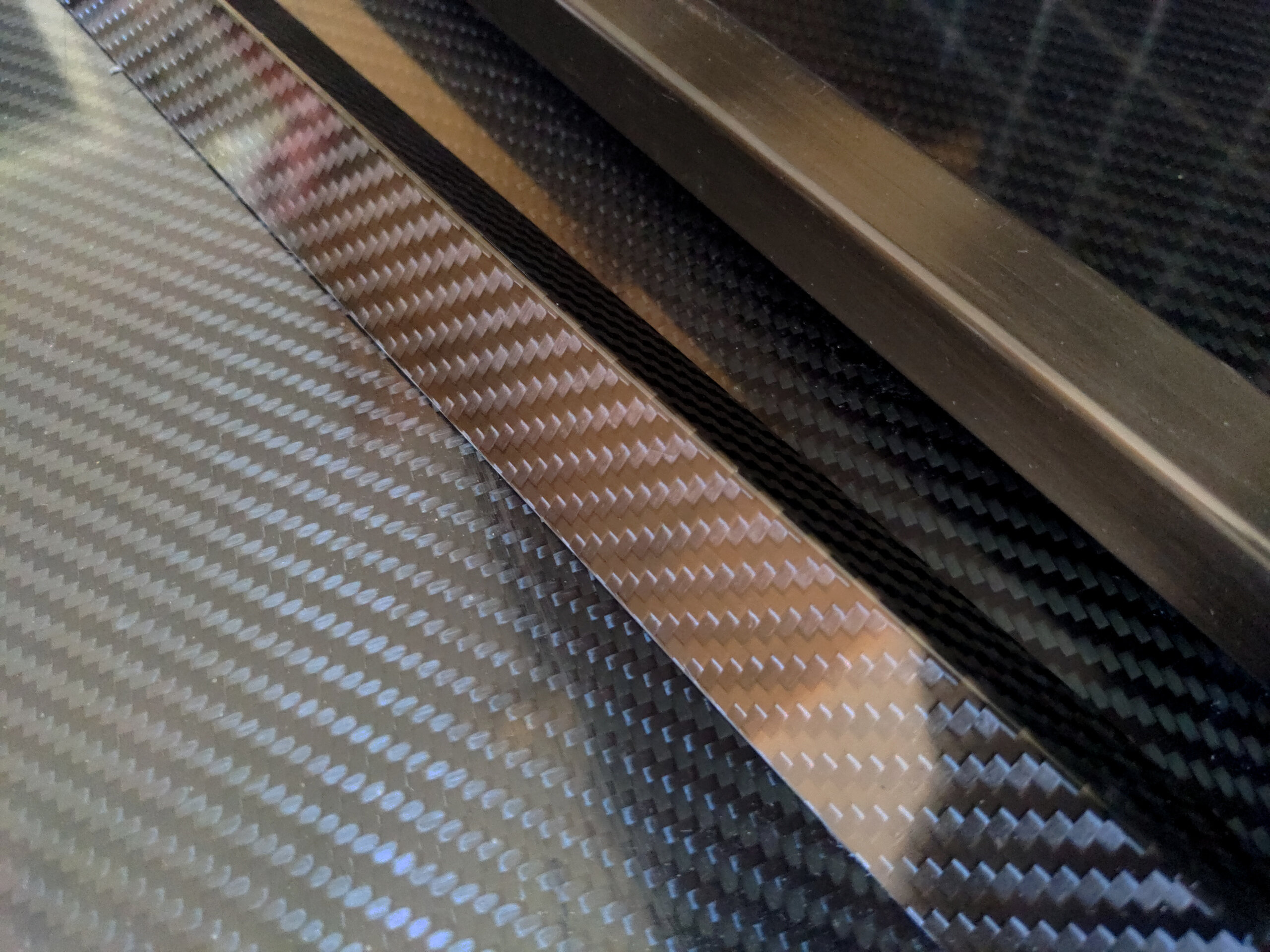
That's right, actual carbon fibre.
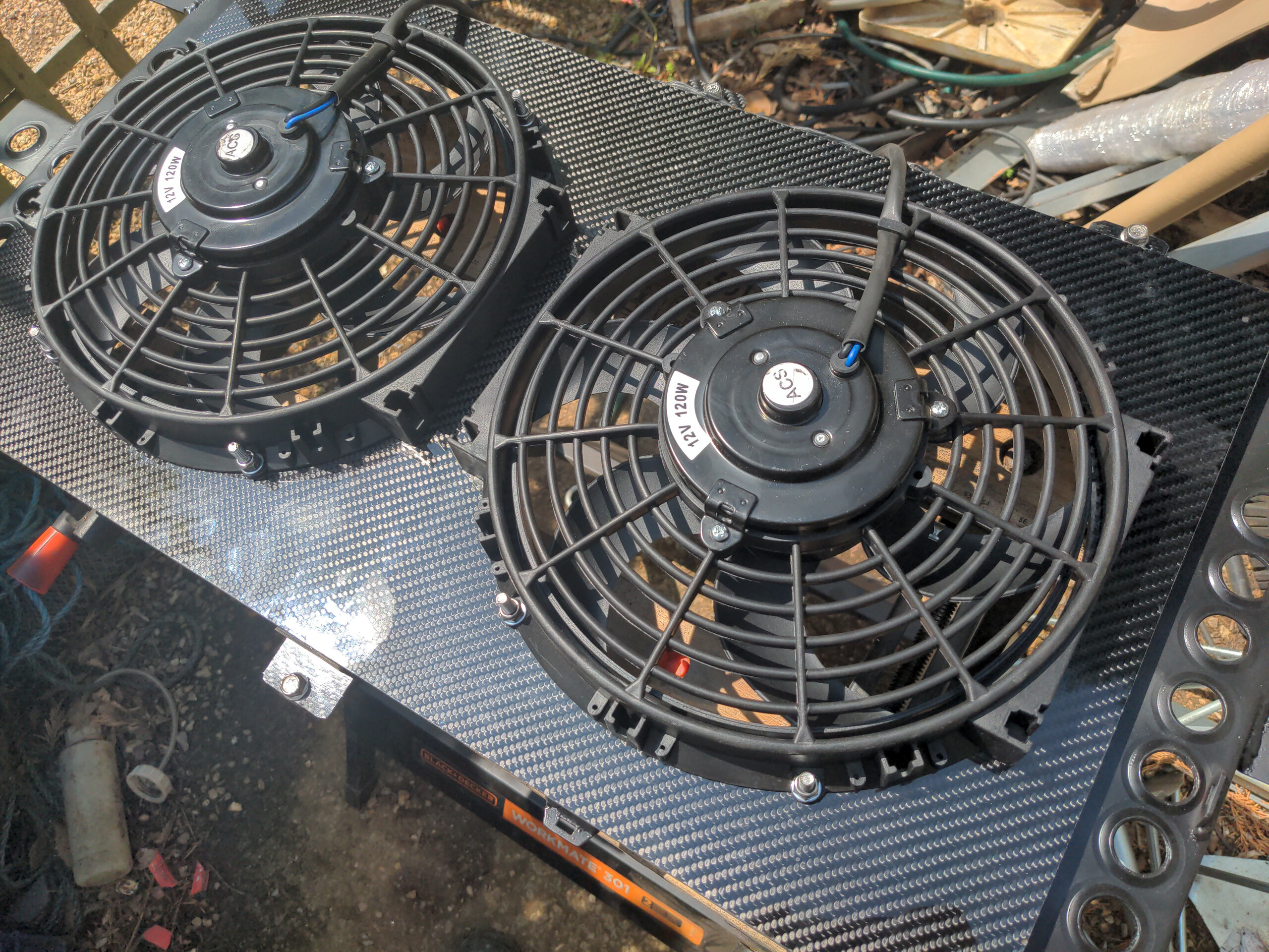
I didn't take any step-by-step pics of this, but this should be fairly self-explanatory: 20mm carbon fibre box section for the standoff, 2mm carbon fibre sheet for the face, and 25x2mm carbon fibre angle for the mounting points, glued together with VM100 adhesive. The fans bolt through with those weird glued-in threaded stud thingies. You can get all of this from Easy Composites, who happen to have an outstanding YouTube channel.
Cured carbon fibre is nicer than I expected to work with! It cuts easily with a normal angle grinder cutting disc or a Dremel-like tool. Easy Composites have a video on the subject. I'm not scared of it anymore, so there might be more carbon fibre parts in my future.
This is crude, and my first attempt at making anything with carbon fibre, but it looks absolutely sick. And nobody will ever see it because it faces the floor! But I know it's there, and it means I get to say "carbon fibre fan shroud".
And that, plus some foam and rubber stripping, is a radiator mounted in the wrong end of a Rover P5.
There is still much to do, because the rest is actually plumbing in the entire cooling system. The radiator needs some modification to the inlets and outlets accommodate a 45 degree mounting angle, an expansion tank needs mounting somewhere, and of course there are no coolant lines.
And in fact I'm not 100% sure there's going to be enough air flow available here. There should be enough underneath to allow cooling at speed, and once I ventilate the boot lid (not at all sorry to anyone who hates seeing perfectly good P5 panels getting chopped up) I should have enough air around for the fans to pull from. That is guesswork, which is not the same as knowing. Without putting this in a wind tunnel, I won't know how well this will work until I actually use it, and it does or does not overheat.
But that's a problem for future Lewis. If I look at everything that I need to do to this car I can be overwhelmed; someone who doesn't really know what the fuck he is doing re-engineering an entire car. But if I break it down into lots of small, standalone projects like this I find it much more manageable, and doing them in whatever order I find most fun on a given day keeps the motivation high.
I know what you're thinking. It's something like "Lewis, this is all totally unnecessary and overkill unless you were planning on, e.g., bolting a massive turbo onto it and getting stupid horsepower numbers which would cause you to actually need all this cooling".
I know.
:)
Part numbers from this post:
- Freeze spray:: Motip 090409
- Radiator: Pro Alloy RADCOSS
- Boot floor corner repair section: J R Wadhams P5BDW37
- Satin black paint: Jenolite 89036
- Red primer: Jenolite 89593
- Carbon fibre: Easy Composites CFS-RI-2-0475, CFBOX-20-17-2, CFANG-25-2-1
- Cable tie mount thingies: Pacific Customs AC750795
- Steel by Thomas B Bonnett, KI Metals and some random eBay seller