I modified another MIG welder, didn't die, didn't entirely succeed
Sometimes, my projects fail. Actually, they often fail, but usually in a recoverable way. This was not recoverable. Not because of the gasless-to-gas conversion (this worked fine), but because the welder I did the conversion on was fundamentally broken.
It turned out that "creates an arc and deposits material" is not the same thing as "actually has enough power to weld two bits of steel together". I checked the former to declare this welder "working" when I first acquired it, and I didn't check the latter. That one is entirely on me. It probably has a bad transformer, which would be an unreasonable amount of money to replace even if I could find one.
I'm writing about it here not because I am doing some sort of brave thing where I'm open about my mistakes. Who would do that! Instead, I'm writing this because I did all the work of a conversion, I documented it on the way, and there's probably someone out there who wants to know if a conversion is possible. It's possible, because I did it. I just didn't do it on a welder that was working properly in the first place. Lessons learned!
This is a free MIG welder.
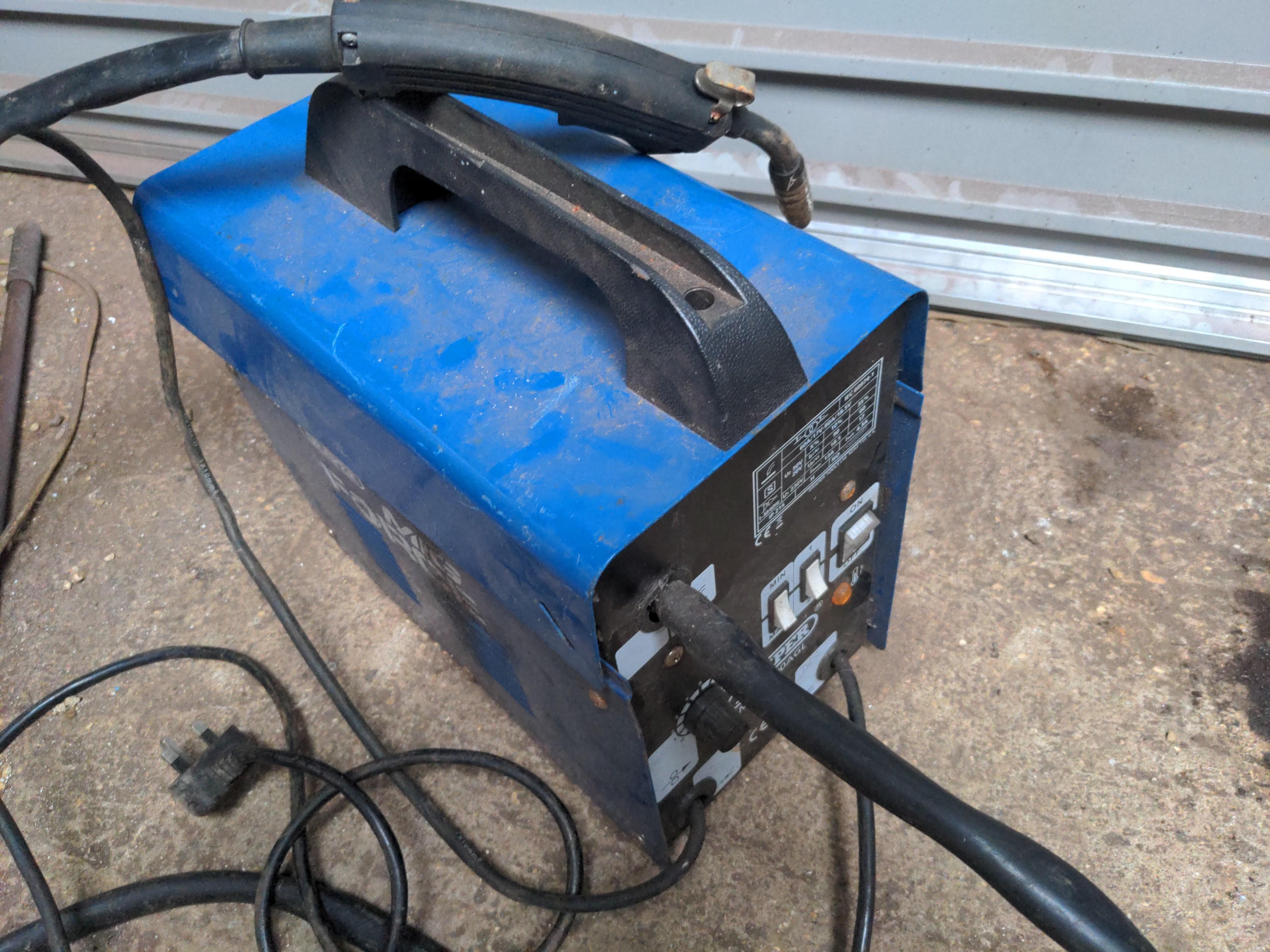
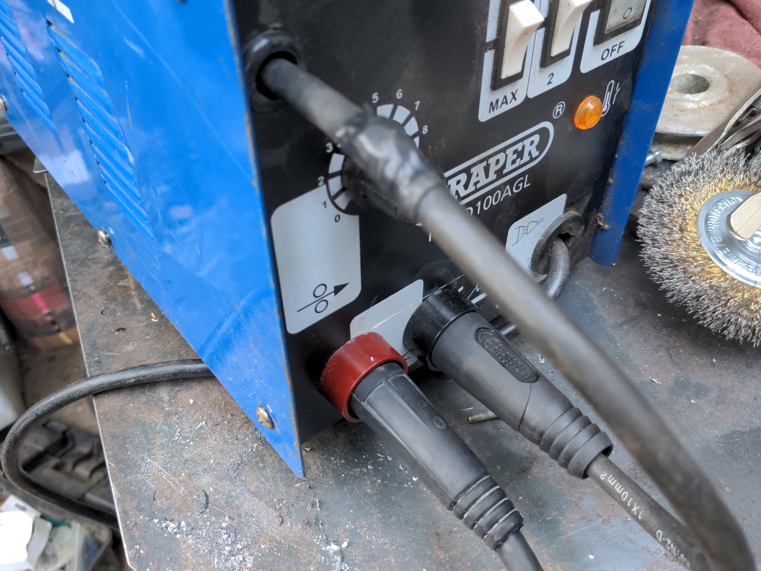
It is a Draper gasless-only MIG welder. I have no idea how old it is, but its model number (MWD100AGL) barely shows anything useful on Internet searches. It appears to be functionally identical to the various Storm Force gasless welders, though this one has "MIG FORCE" written on it (which also returns few useful Internet search results).
It's actually my second free MIG welder. I wrote about the other one. My old man bought this one a long time ago, discovered he didn't like flux core welding, and then left it in the corner of a shed. This was going to be broken for parts because most of the parts fit other hobby MIGs of a similar configuration, including his.
The reason why the parts are interchangeable is that most of them are actually designed and built by the Italian company Telwin. That means that much of what I say here will be applicable to other hobby gasless MIGs. For example, the Sealey Supermig 100 has an identical body and front panel to this Draper welder, right down to the overheating light being in the same position; I will put money on the internals being identical.
If your welder has simple white switches with "MIN/MAX" and "1/2", then it's probably internally identical to this one; if it's not identical the same principles will apply. Inverter welders and welders with digital controls will be different. Take your own risks with those; I can only tell you about what I have worked on.
Anyway, this welder being stripped for useful parts and the remains ending in a bin seemed a bit of a waste of a welder, so I acquired it for free for two reasons:
- It's free so why wouldn't I
- I wanted a welder to set up just for use with stainless steel, for Reasons, and changing over gas and wire every time I want to change materials is effort
And if I blew it up modifying it (and I survived it blowing up) the worst that could happen is the fate that would have befallen it anyway: spare parts that'll fit some other MIG. Which is what it ended up becoming anyway!
What you'll need
- A pair of Dinse-type connector sockets (£6.50 for the pair)
- A Dinse-type connector plug (£6.50 for the pair)
- A replacement earth clamp with a Dinse plug (£14)
- A Euro torch conversion kit. I got mine from a supplier on eBay who does the torch, connector, and solenoid for £85 (as I write this in July 2025). If you assemble this from the cheapest Amazon parts you can probably assemble your own kit for £60 or so.
- Heat shrink, heavy-duty ring terminals, and other electrical miscellanea (I already have these, and I suspect you do too; these are probably pennies bought locally)
So that's £112 for my fancy version of the conversion, and you might be thinking that even though I got the welder for free, this is actually about the cost of a cheap Amazon ALLCAPS brand welder brand new. Well, I don't trust a HORNTWIG or ZEEPHNOO or whatever the fuck to not kill me instantly. And anyway this is really a learning experience for me; I'm doing it because it is fun, not because it makes financial sense.
Still, as I go I'll tell you about ways that you can do this cheaper than I did.
On drilling holes
Any time I say "drill a hole" in this post, I actually mean "drill and deburr a hole". You don't want sharp edges on your hole even if you are putting a grommet in it. And the thin metal used for this case likes to leave debris on the outside rear of any holes you have drilled. In some cases, this will stop connectors from seating flat and secure against the casing.
How you deburr them is up to you. The most convenient method for me most of the time is a finger sander, because I have one and it gets into most places. But small files and coarse sandpaper work fine here too, and in some cases that's what I used.
Safety
This is all at your own risk. I'm not making you do any of this, and if you electrocute yourself or blow up your welder that's on you. Remember a typo or a bad wording could completely change the meaning of something I write, and I write half the things I do after long busy days so that's basically a given. Don't take anything I say for granted; investigate it yourself.
Always unplug your machine from the mains before working the internals. Because you'll be working in close proximity to the power switch, turning it off at the switch on the welder is not sufficient.
ALWAYS leave your machine for at least a minute after removing power before opening up the machine; capacitors or whatever can hold a charge for a while.
Reversing the polarity
Let's take a look at the first of the two problems here. This machine is designed for gasless only operation, and gasless welding has the torch and earth clamp polarity reversed from a gasful MIG. The torch is negative, and the clamp is positive. In gasful operation, the torch is positive and the clamp is negative. If you try welding with solid wire a shield gas in this polarity you might deposit molten metal onto a piece of metal in some form, but the welds will be worse than a mess.
The very cheapest option would be to chop the two thick welding current cables, and rejoin them back-to-front. That would work, but it would be ugly. It would also be permanent; you would not have the option of using flux core wire after the modification. I barely use flux core these days, but it is very handy when I run out of gas and I need things done right now.
Instead, let's look at my other free welder, which has the option of switching from gas to flux core operation:
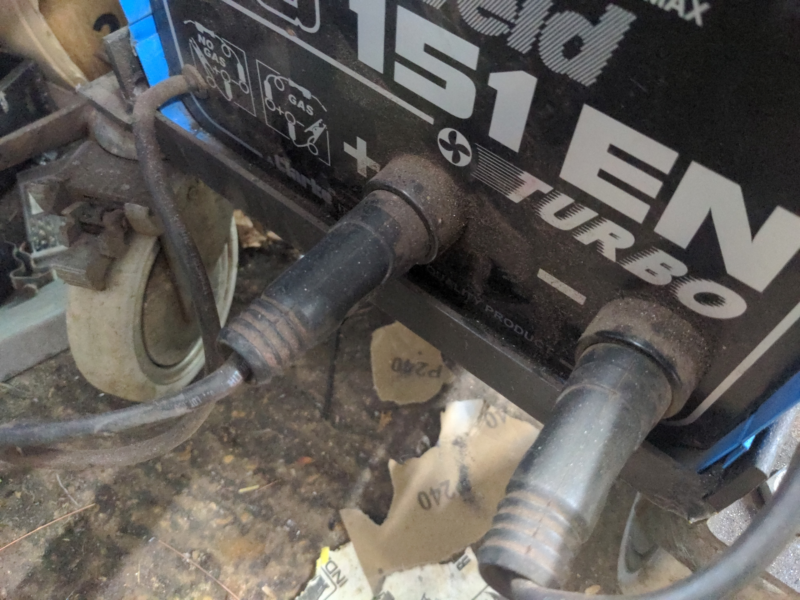
See the two sockets on the bottom? One goes to the torch, and the other goes to the clamp. When I want to move to flux core wire, I can simply swap these around to reverse the polarity. We can copy this setup, because it's as good as any and it is tidy.
And when we copy it, we can copy it incrementally. Just watch!
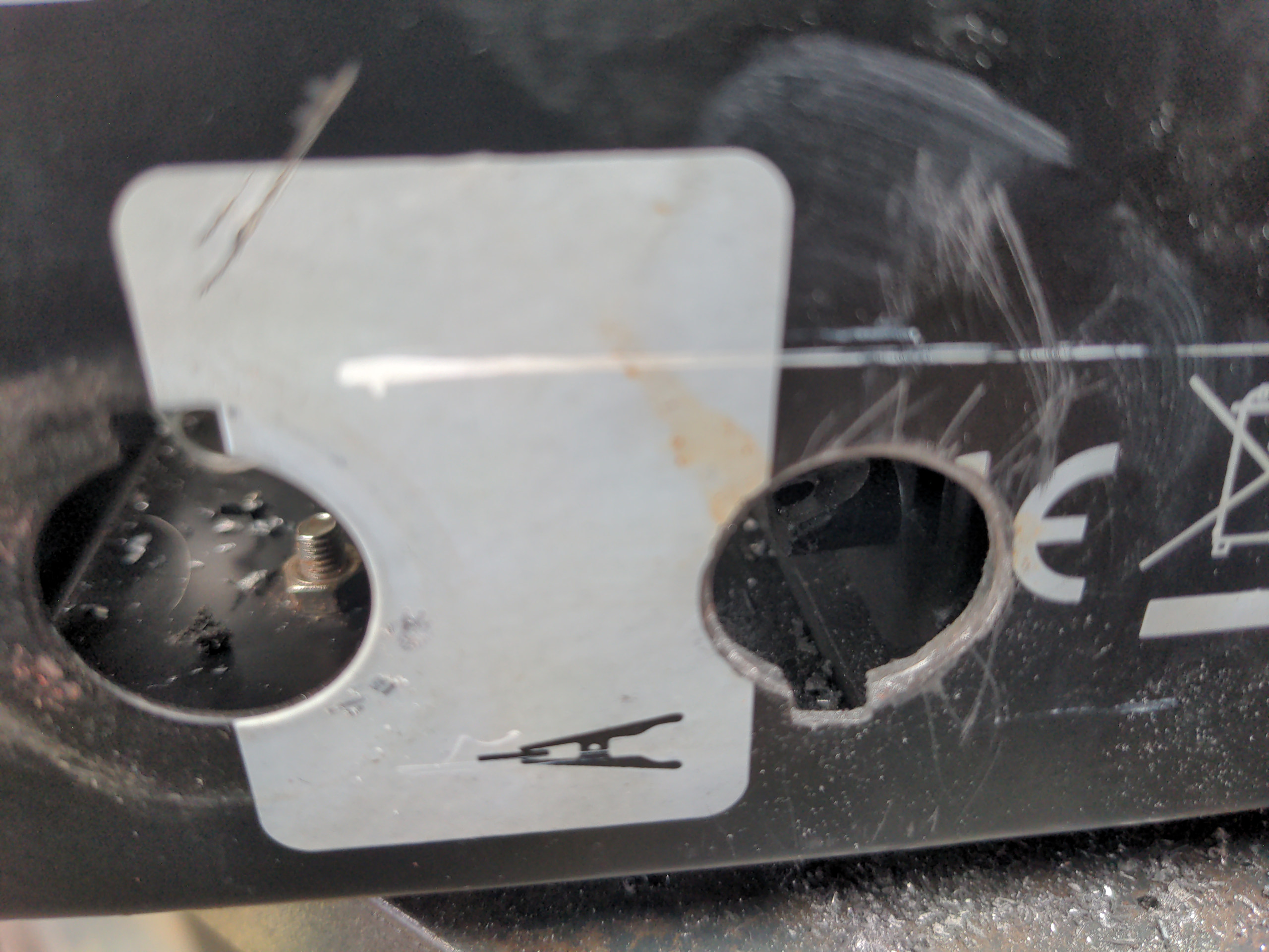
First, we will take care of the earth clamp (which is positive, remember). This is the easiest one, because you can see exactly where it goes; it's the only one of the two welding cables that comes out of the machine. Here's where it comes out on the Draper:
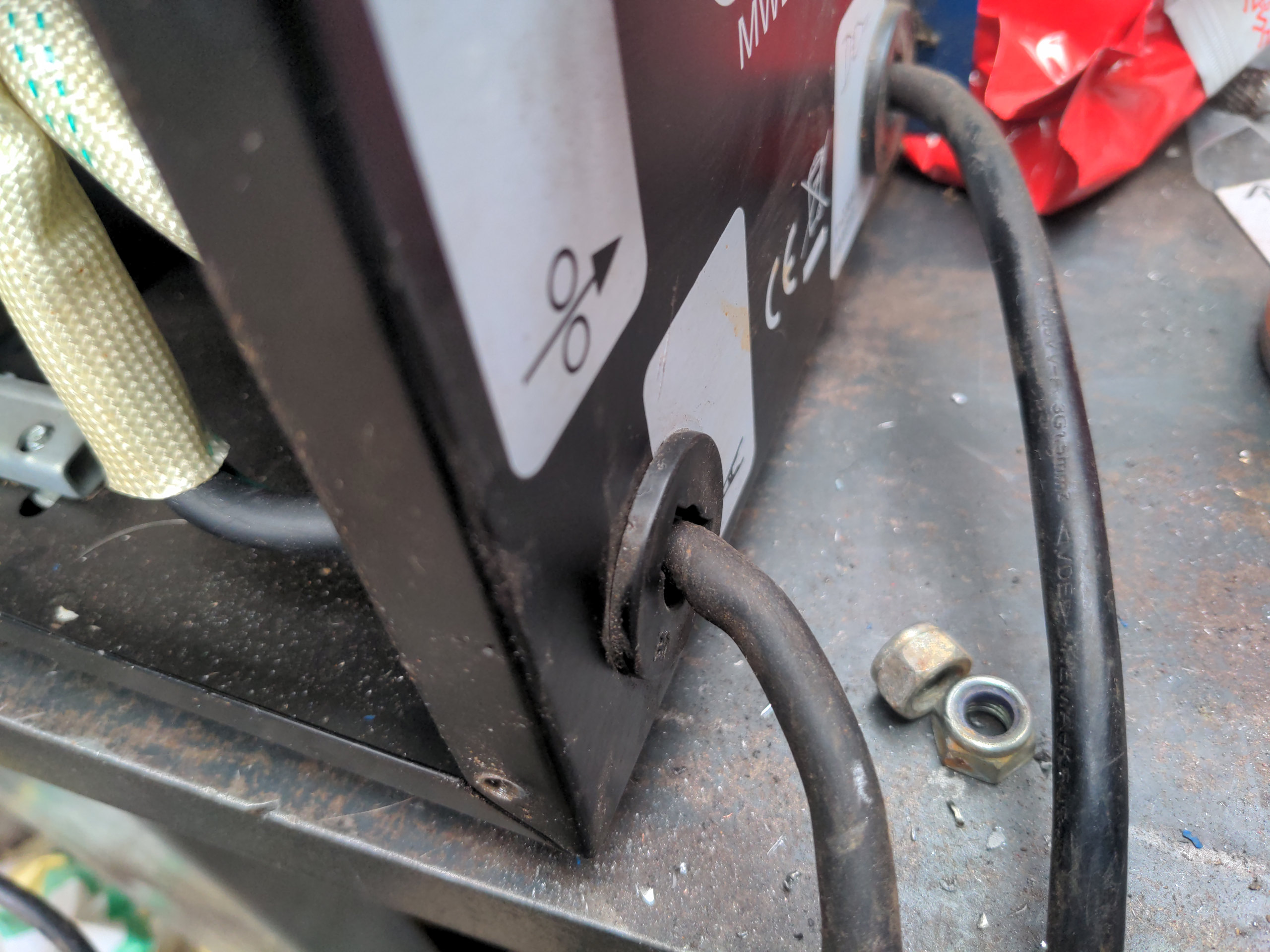
So cut off your clamp's lead about an inch in front of the machine, pull the cable back into the machine (and out the side). The trick here is that the hole you will find after removing the plastic grommet is exactly the right size and shape for installing a Dinse-type plug! This isn't an accident. The same front panel stampings will be used for the more expensive machines that have a plug here. It's a cost-saving measure among many other cost-saving measures that allow you to pick up a MIG so cheaply.
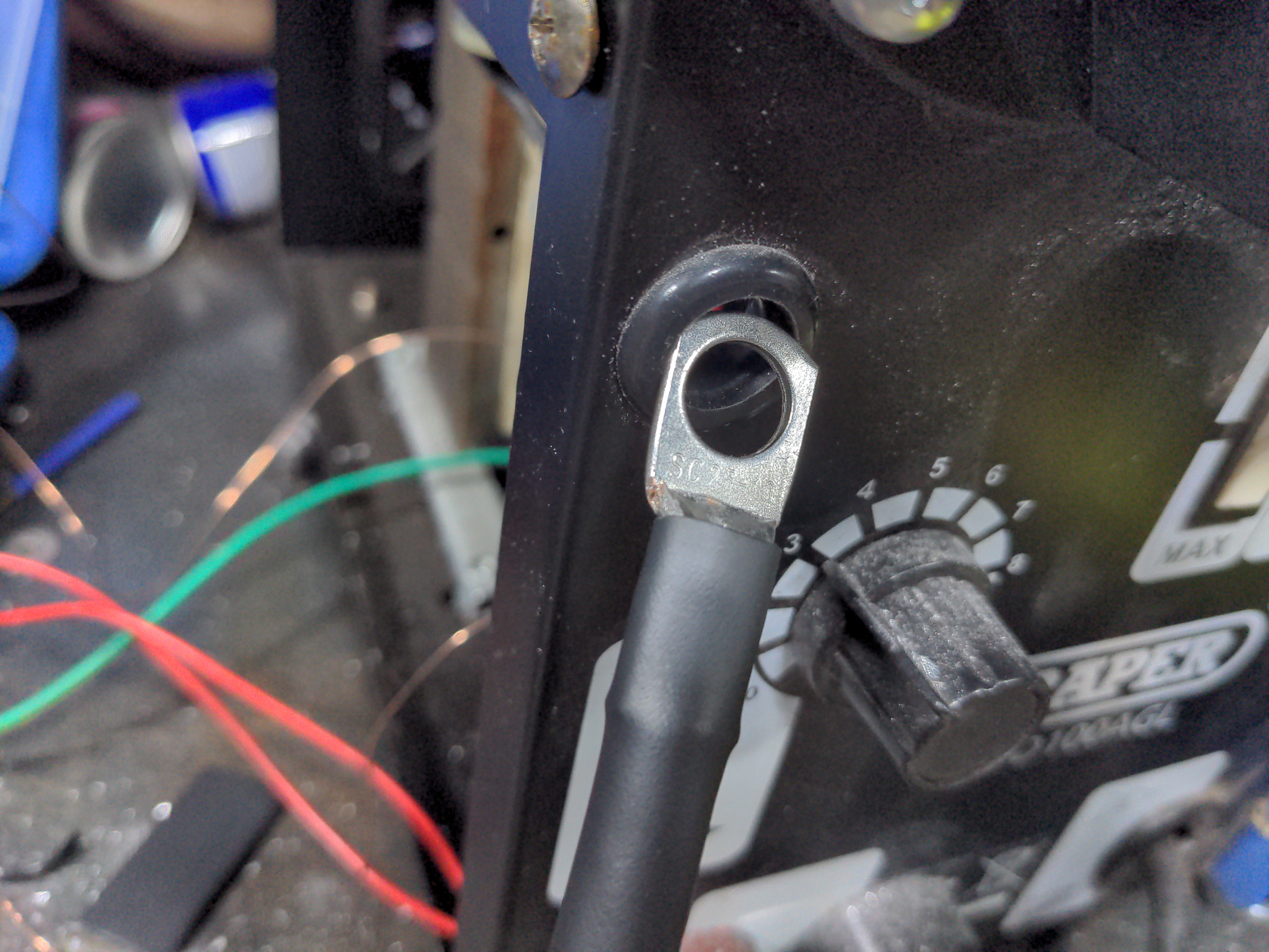
This means that you can just push the Dinse connector plug through, thread the big nut onto the back, then crimp a heavy-duty ring connector onto the stub of your earth lead (the part remaining that leads into the internals) and bolt that onto the connector. When you're done it'll look something like this:
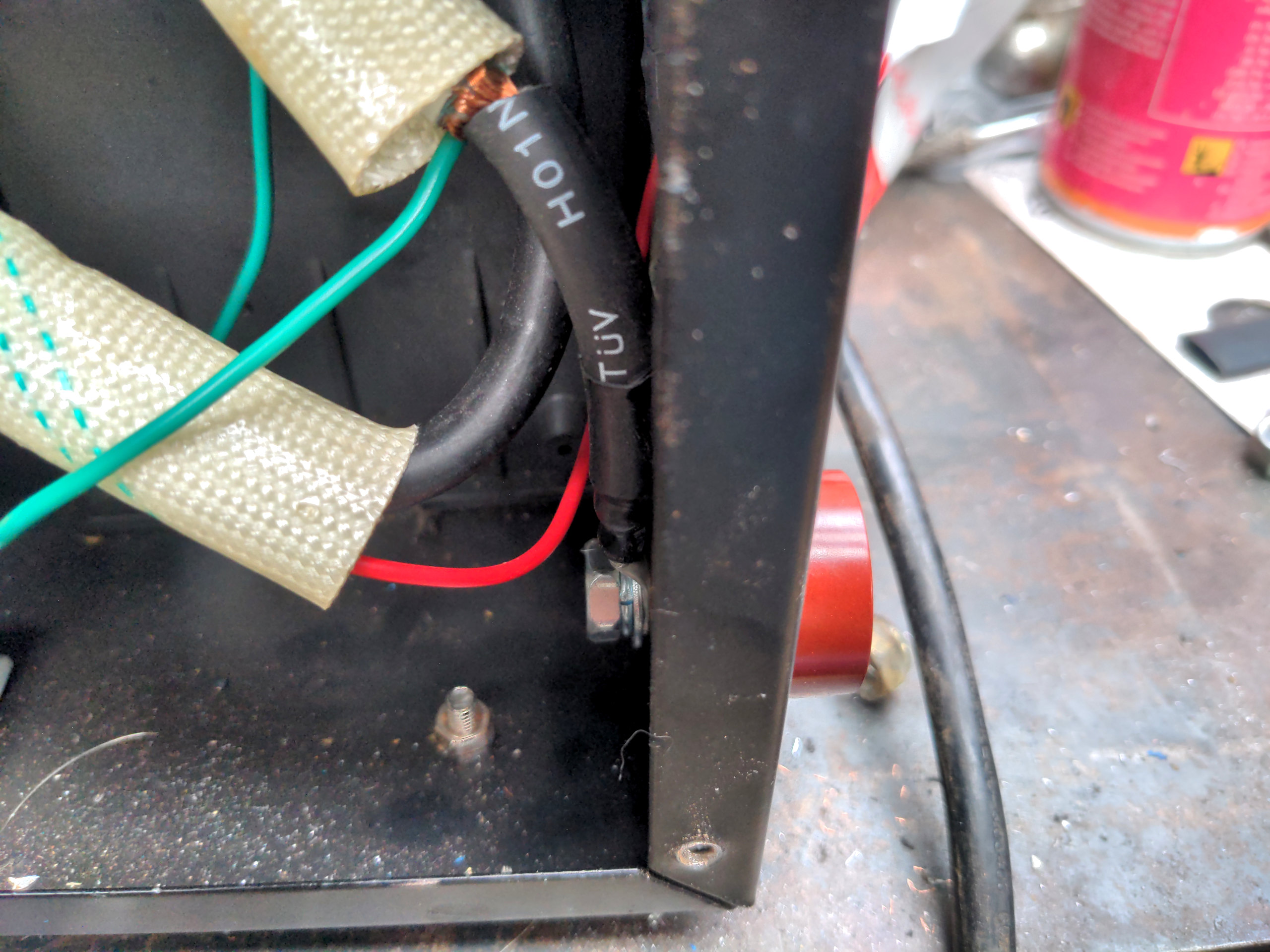
Note that I used a red connector; reminder that the earth clamp is positive in the flux core configuration. The exposed copper wiring that you can see just before it was not my doing; that is just how this was made. But I later fixed this with electrical tape because it made me nervous.
Cut off about another six inches of the cable and put it to a side; you'll need this later. Then attach a Dinse-type plug to the remainder of your lead.
Cheapskate measure: I bought a new clamp and lead here, because it has the connector already attached and it's less effort. You could save about a tenner if you don't mind shortening your lead a little.
Above we said we're doing this incrementally. We've changed one thing, and we shall find out if that one thing works; it makes fault finding much simpler. So now would be a great time to check that your welder still works. With flux core wire, the welder should work exactly the same as before.
Yep!
Next is making the torch pluggable. First you will need to drill a 19mm (3/4") hole in the front of your case, to the right of the socket.
You don't want this to be less than 40mm centre-to-centre, and ideally you want somewhat more. If they are too close, the easiest path between the two things under some circumstances will be between the exposed parts of the plugs, and you definitely don't want that. In the case of this Draper machine, a centre-to-centre spacing of about 45mm spaces them out a good amount without making it impossible to get the nut and bolt on the back of the plug. But I wrapped the positive terminal in electrical tape to be on the safe side!
After you have made a 19mm hole, you will want to make a little outward notch on the edge of the hole. Dinse-type sockets have a corresponding notch to stop them spinning. A small file does this fine. I did mine in the downwards direction because that is easier than filing a notch upwards.
Here's how the hole will look:
You'll now want to install the Dinse socket in this hole.
Now find the cable which goes to your torch. On this Draper machine, it's this one which goes up into the top deck and disappears somewhere into the wire feed mechanism, outlined in green here:
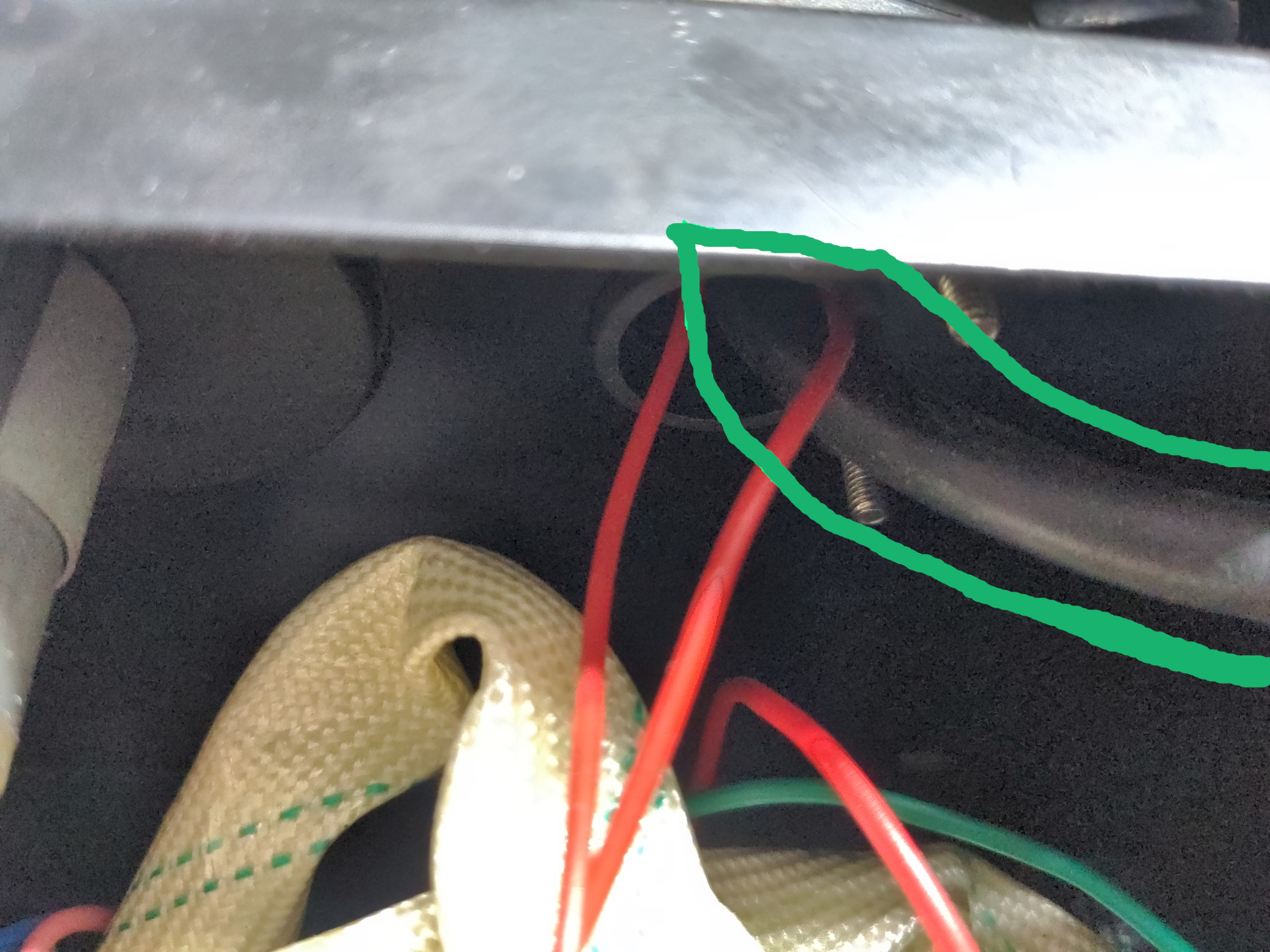
Trace this cable back to the transformer. Then trace it forwards again and cut it to leave you just enough length to install a ring terminal on the front and still reach the rear of the Dinse socket you just installed on the front panel. Crimp or solder a heavy-duty ring connector to the section of the cable from the transformer and bolt it on the rear of the Dinse socket.
Next we need to drill a hole in the case large enough to accommodate this cable, and install a grommet there. You want this to be somewhat below the top deck of the welder (where the wire and wire feed live). You'll see where I installed it in a picture in a moment, and you may as well copy that.
Now take the end of your torch cable (that one we just cut in half) and feed it out the machine through the grommet. You will need to extend this cable to be able to reach the socket you just installed on the front of the machine, with a Dinse plug attached. That's why I suggested cutting off six inches from your old clamp cable earlier. You can re-use this to extend the cable. I would recommend soldering and heat-shrinking this, if you can. Otherwise a crimped-on terminal will work fine. However you do this, be sure to insulate it. I did solder-and-heatshrink, then wrapped this in electrical tape to give it better abrasion resistance.
Here's how that'll look when you are done:
Note that the polarity is still in flux core configuration! The torch is going to negative and the clamp to positive. This is on purpose, because now we are going to test that this works with flux core wire.
Yep!
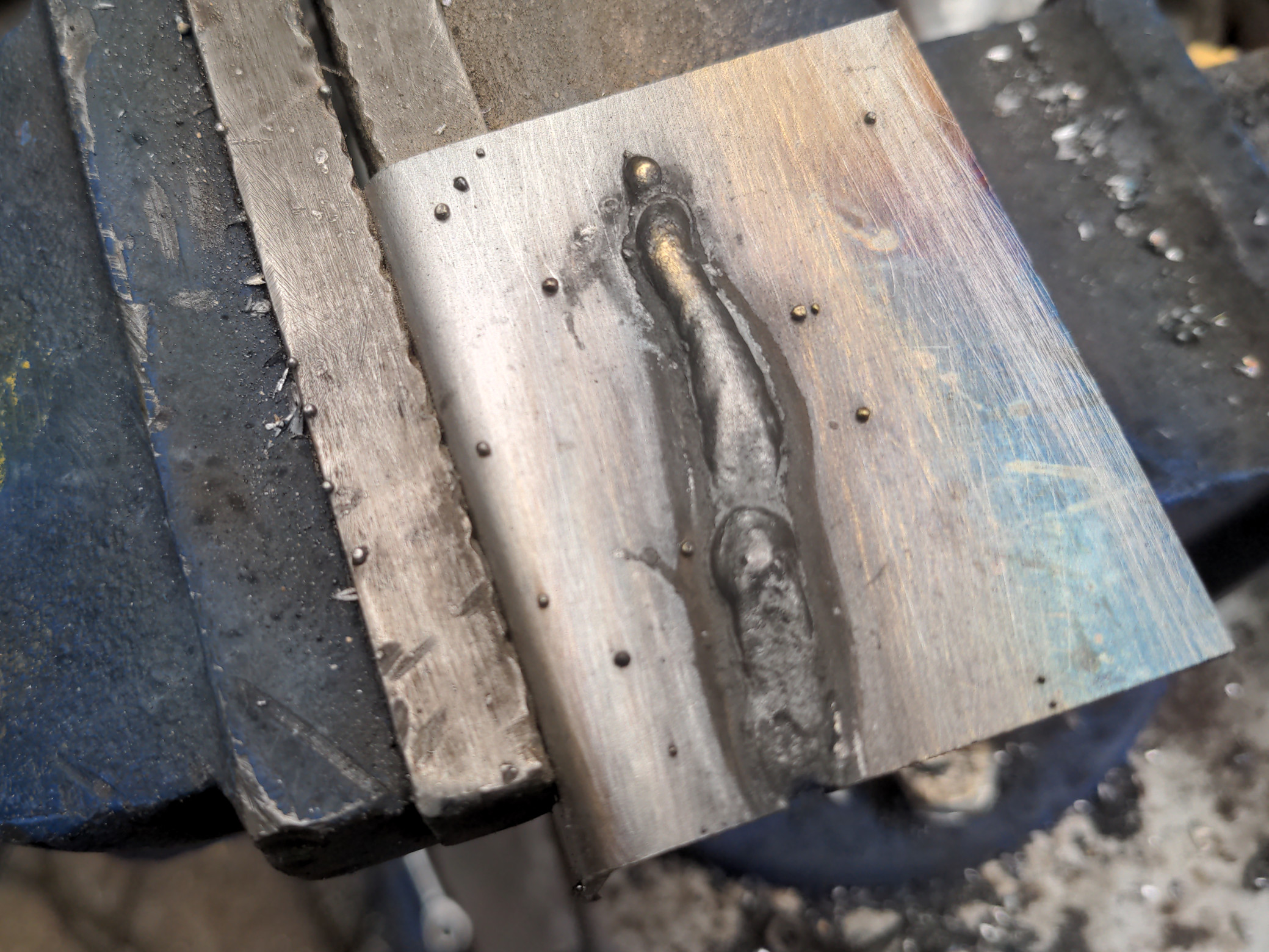
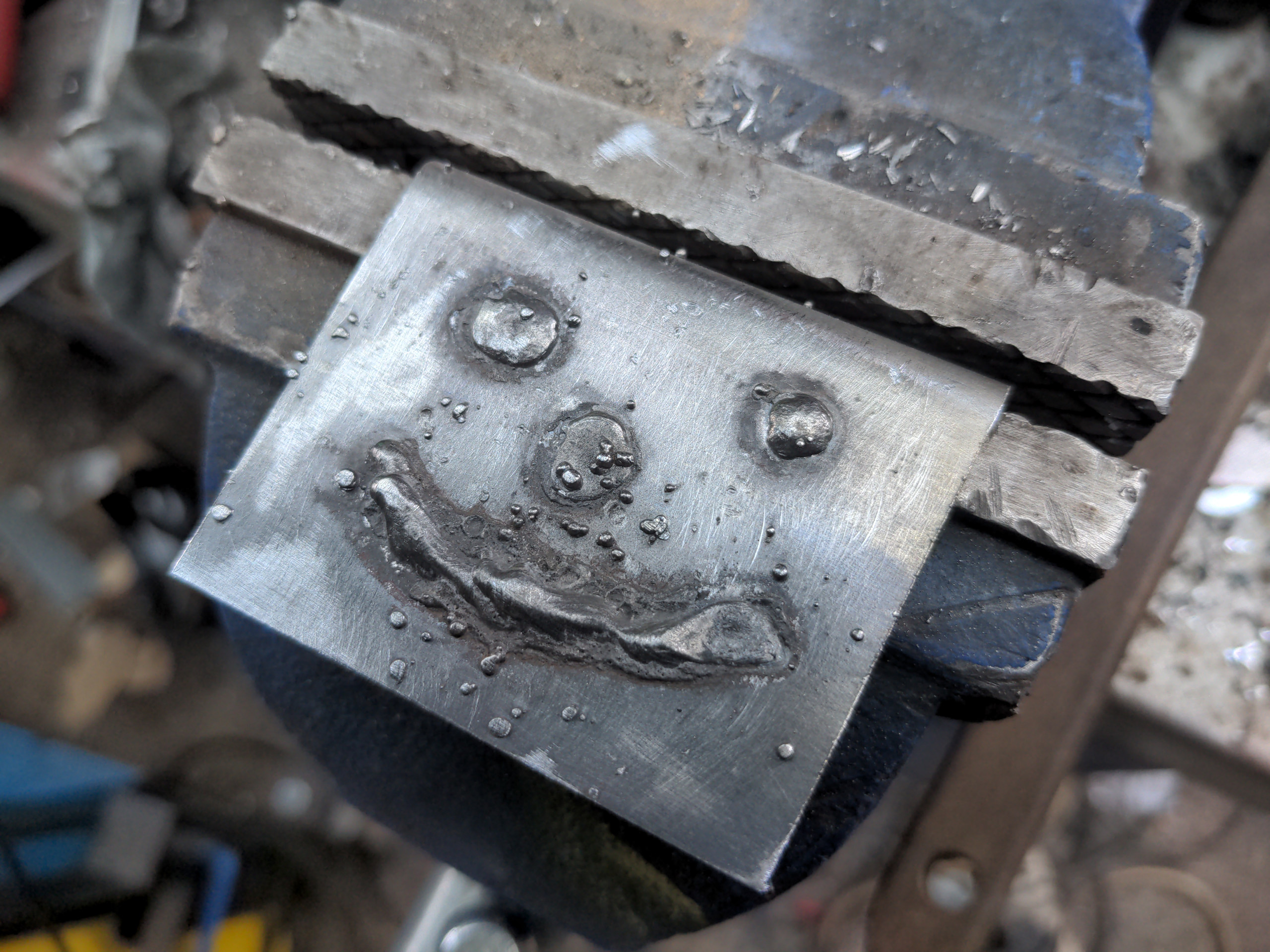
After testing that, we will switch the polarity. Unplug both the cables, then swap them around - torch to positive, clamp to negative. You will also want to switch your welding wire over at this point to solid wire (the type you use for gas). Your machine should now lay down a weld, though a messy one that will be full of craters because of the lack of shield gas.
Success! You have reversed the polarity of your welder.
Changing the torch
...but you don't have a gas feed to it yet.
The absolute cheapest way of doing this is to purchase a torch that hard-wires into your machine and has a gas feed that goes directly from your bottle into the torch, and has a little valve in the torch body itself that allows gas to flow when you press the trigger. That'll cost you about £25 from your favourite Internet retailer (search for "Clarke MIG torch" or "14AK torch" for better results; the ones you want will be the ones with wires sticking out at the machine end). You're on your own fitting that, because I've never fitted one.
That is not what I will do here. Instead, I am going to fit a "Euro" (Binzel) type torch. That has lots of advantages. One is that the torch can be replaced without opening up the machine and cutting electrical wires. One is that consumables and spare parts for the torches are easier to find and all interchangeable. And the build quality of the torches is invariably much better, too. In fact, even if you are exclusively doing flux-core welding, for whatever reason you might have to do that, a Euro torch by itself is a substantial upgrade.
Your first job is to cut off the torch. You could carefully de-wire it, but you won't need any part of the torch again anyway. Cut it just in front of the machine to ensure that you have plenty of spare wire left over. Push the remainder back into the machine and move to a side.
While we're here, let's take a look at the wires which go into the torch.
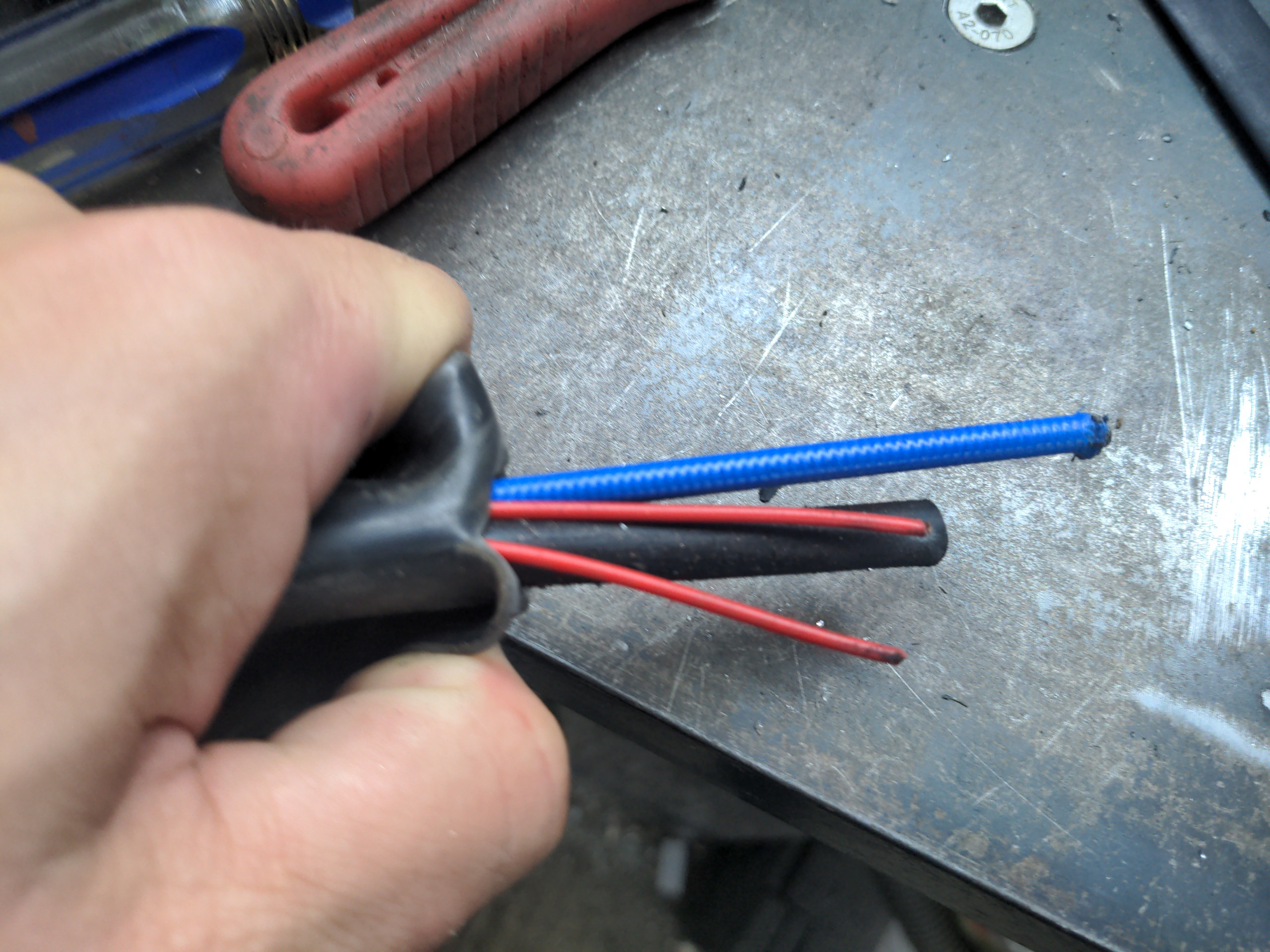
Ignore the blue one which looks like a bicycle brake outer cable; that's the one that feeds your welding wire into the weld. You will have three electrical ones. There are two thin wires, which are red in this machine. These are your trigger wires. One of these thin wires (it doesn't matter which) has a small positive DC voltage going to it. When you pull the trigger on your gun, these two wires are connected and that triggers (via your main PCB) your wire feed and your welding current.
These were the other two wires you saw in the photo earlier on (outlined in blue):
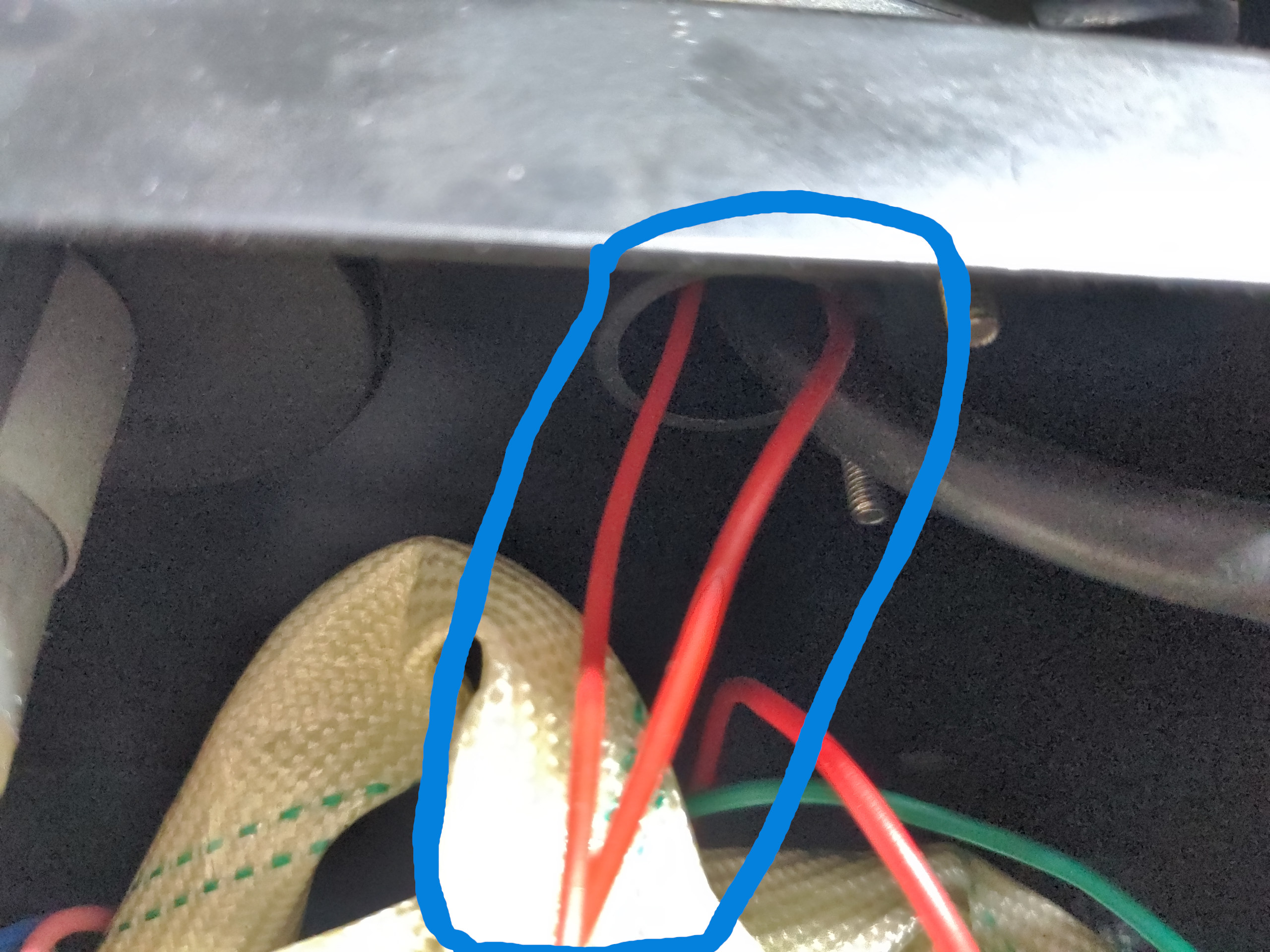
The single thick black cable is what carries your welding current. The other end of that is what we routed out of the machine and into a red Dinse socket earlier. We'll call it the "power cable" hereafter. You don't need to know that right now, but this is a good time to establish purposes & terminology.
Right now, you want to open up the hole on the front of your welder (the one the bundle of torch cables used to feed through). It needs to be opened to about 40mm to accommodate the body of a Euro torch socket. It will need to be larger than this in the final setup (read below), but this is to permit aligning the big plastic Euro torch mounting point on the front. I did this with a step drill bit; you can use a die grinder, or a file if you have more patience than I do.
Once you push through the connector and line up the plastic mounting point on the front, you will notice two obvious problems fitting it on this particular welder. The obvious one is that it hangs over the edge:
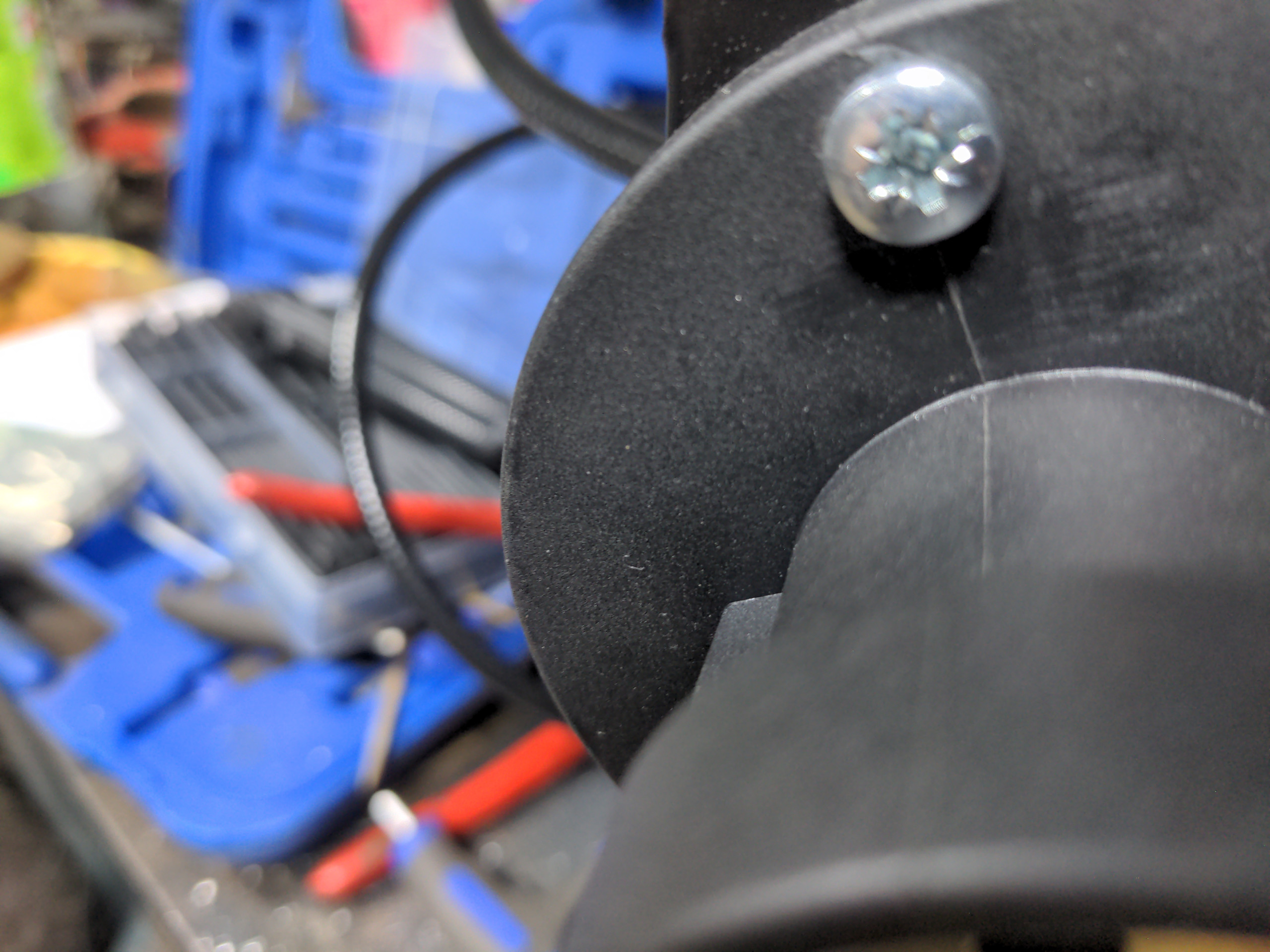
Which is to say the mount is too large for the body. We could solve that by relocating the wire feed mechanism, but that would be effort. We could also solve that by cutting a chunk out the side panel, but that would be ugly.
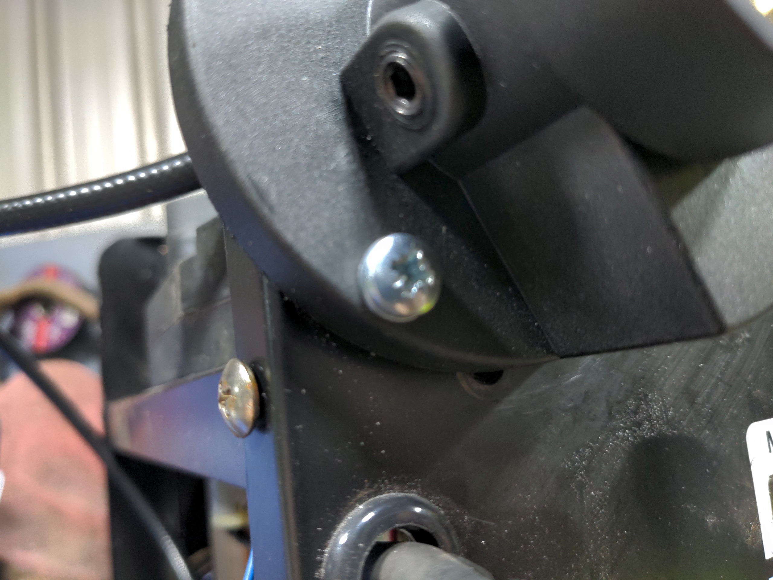
The less obvious problem is that a screw hole is being overlapped (the screw has been removed in the pic below). This is actually the bigger of the problems, because it'll prevent the Euro torch socket from sitting flush with the face of the welder, and so it won't naturally take a straight path into the welder.
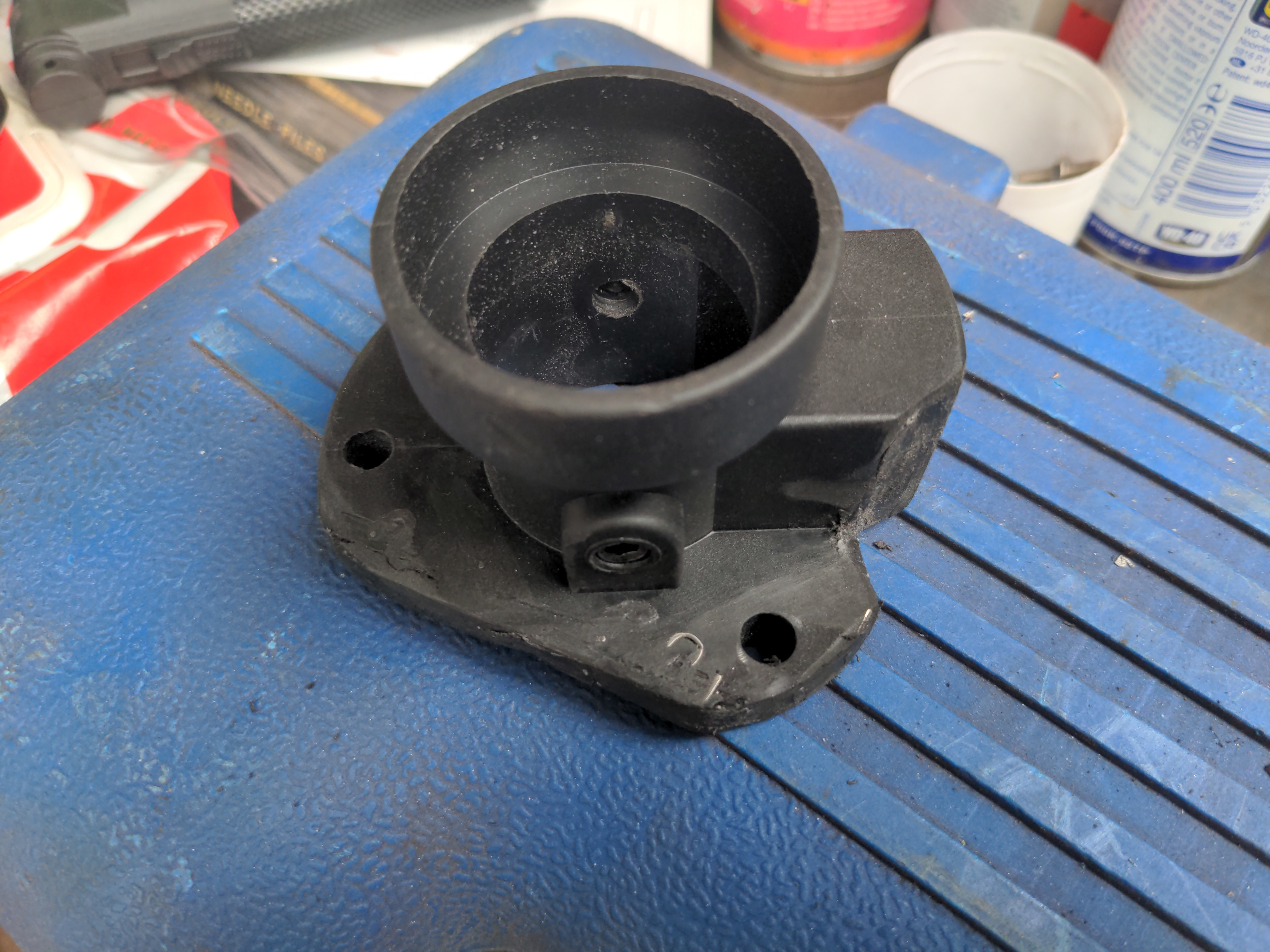
So, rotate the plastic mount until it is in a position where all three bolt holes are on the face of the machine. When in position, clamp it and drill those holes; you might as well do that now. Mark out the overhanging section, and also roughly mark out the area where it overlaps with a screw. Chop off the overhanging part, then use a file or a finger sander to notch out the screw-overlapping area.
You don't want to leave it like this, because you've removed much of its strength. How you tidy up this cut edge is up to you. I used one of those cheap sketchy-looking plastic welders to stick in a reworked section of the plastic I cut out of the side, and used some random piece of plastic (a disposable spreading spatula from a pack of two-part epoxy) to reinforce the area around the screw. It doesn't look too terrible. I'm really impressed by how well cheap plastic welders work, anyway!
Next, bolt up the plastic socket into place on the body of the welder. Open up the top of the welder, and remove the plastic cover on the wire feed mechanism (this is six screws, two of which are self-tapping and four of which have a tiny nut on the underside). Slide the (usually) brass body of the Euro socket into the plastic socket.
Now rotate the brass body until the guide tube (I hope your kit comes with a guide tube) is perfectly lined up with the recess in the plastic of the wire feed mechanism's plastic body. Once that looks right, you will likely have a grub screw or two to tighten up on the plastic socket.
Here's a picture:
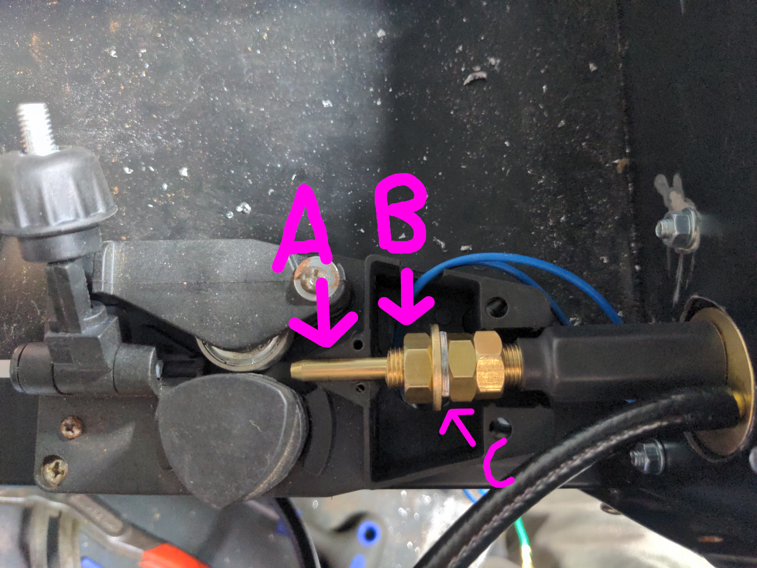
↓ A points to the guide tube. This guides your welding wire (the consumable that gets fed into the welding arc) into the torch. If your Euro socket doesn't come with this you need to get one, but any good kit (like the Yorweld Supplies one) comes with one. The plastic area on which it sits will probably (depending on the diameter of your guide tube) need to be filed wider to accommodate it. There's already a groove there; just attack it with a small circular file until you can easily put the top cover back onto the wire feed mechanism.
Your guide tube will probably need to be cut to length. It should be just long enough that when you attach your torch it clears the roller by about 4mm; this will keep things tight but not hinder removing the roller.
Once your guide tube is shortened, attach your torch to the Euro socket and tighten it fully. Just trust me that this will make your life easier.
↓B points to the threaded tube that will have two or three nuts on it. This will need to be cut to length, but not just yet. What you want to do next is to grab your welding current cable (the thick one going to the torch, which now exits out the machine and goes immediately to the positive plug on the front), and shorten it such that it can reach point B without being either over-stressed or with excessive spare cable. Then add yourself a little bit of spare wire to be on the safe side. Then attach a ring connector onto the welding current cable, one large enough to slide over the threaded part at B.
What you don't want to do here, by the way, is pull the cable out of the machine entirely, and then put a ring terminal on it. If you do that, you won't be able to get the cable back into the machine to attach it to the Euro torch, and only the dumbest kid in the class would do something like that.
ANYWAY, once you've got your terminal on, you'll want to slide it over the threaded rod at B. In situ, this is indicated with ↑C. You'll need to adjust the two or three nuts until it all sits right; you want the welding current cable to sit right in the middle of the hole into the bottom of the machine. Just fiddle with stuff until it feels right. Once it's in place, use a marker pen of some kind (I prefer a thin black paint pen) to mark a point on the threaded tube leaving about five "spare" threads, take it out, cut it to length, and refit it all.
If none of this makes sense, just look at this unannotated version of the photo at full resolution. It probably makes more sense than me explaining it.
Next put the cover back onto the wire feed mechanism to make sure that everything fits (you might find yourself doing some adjustments to the plastic cover with a file), then take it all apart again! That includes removing the plastic socket holder from the front. Cut the threaded rod to the length you marked.
To avoid arcing, you must now bore out the main hole on the front of the machine for the Euro socket to about 45mm or more. We left it at the old size because that made fitting things up easier, and we can now commit to it. I would normally use a step drill for holes this large, but I found that the thin metal that the front case is made of likes to grip the drill. Because this welder is so light I found that when the bit got stuck it would throw the machine up in the air. Fun! But not conducive to getting the actual job done. I found that the easiest way of doing this was to drill a 6mm hole into a piece of random scrap steel, clamp it such that the 6mm was dead centre in the Euro socket hole, and use that to guide some larger-than-45mm hole saw into enlarging the hole.
Now you can install the Euro torch socket again. Assembly is the opposite of disassembly which was the opposite of assembly. With that in place, you will be able to join the two trigger wires from the machine to the two trigger wires from the Euro socket. I prefer using uninsulated connectors and adhesive-lined heat shrink for this, but you can use insulated inline joiners if you like. It doesn't matter which of the two wires from your Euro socket attaches to which of the two wires from your machine. You'll probably want to shorten these wires, because they'll certainly be excessively long and you don't want that.
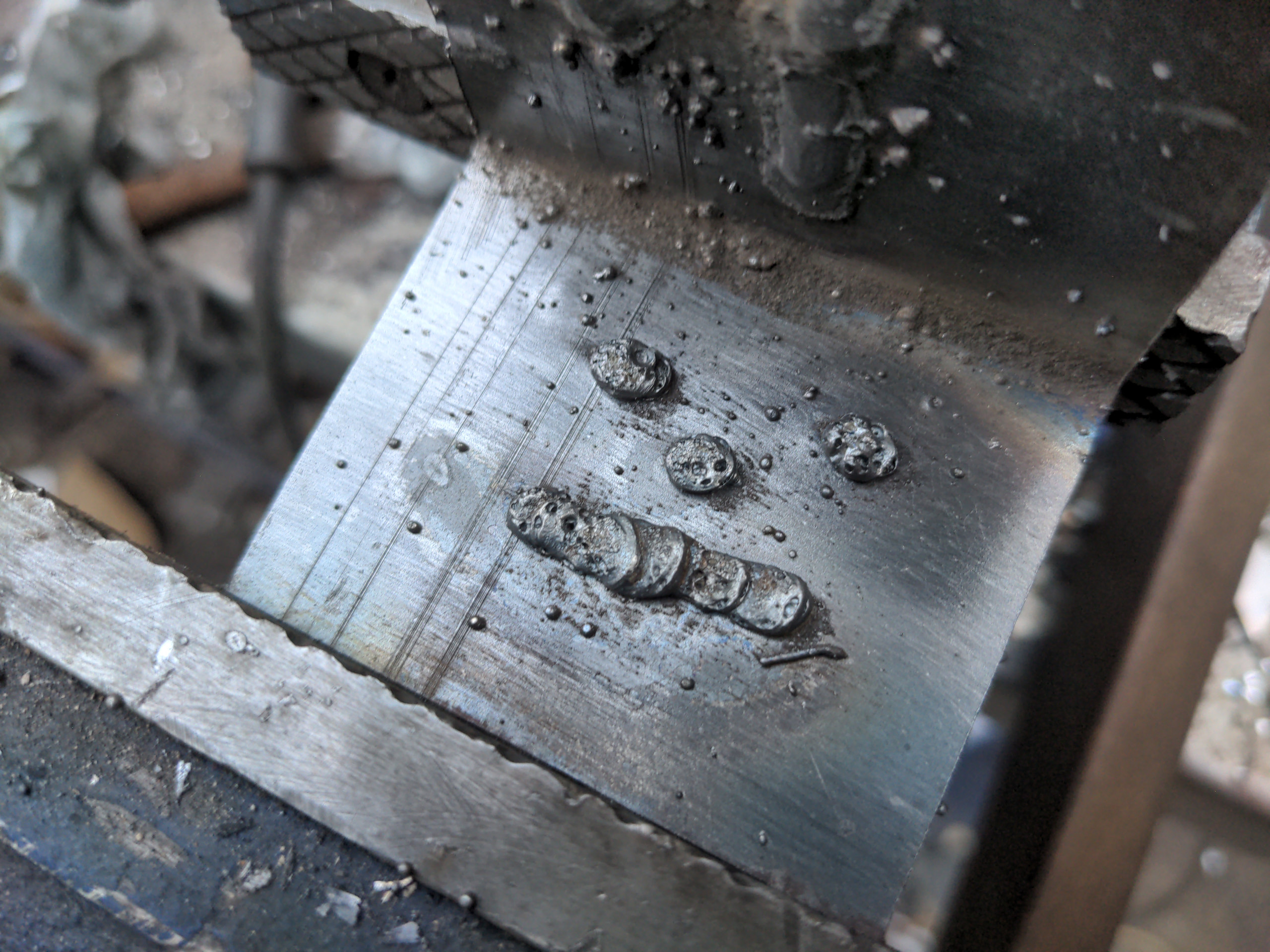
And finally (for this part of the modification) you can attach your welding current cable and reassemble your wire feed mechanism. Attach your torch, feed wire into the torch, and test the welder again to ensure that your welder still works with a Euro torch.
If you lay a crude, gas-free weld exactly as you did before you changed the torch you are ready to proceed. Success!
Adding the solenoid
...except you still don't have a gas feed to the torch.
If you noped out on all the Euro torch stuff above and just decided to fit a 14AK torch, you don't need to worry about this. Those cheap torches have gas flow control built into the switch; when you press the switch, you are also pressing the trigger for a little valve that lets gas flow directly into it. All that's needed is to hook up the gas feed from your regulator into the torch.
Euro torches don't have any gas flow control built in. Instead, they assume that the welding machine will take care of supplying gas to the torch. That is done with a little welding solenoid that looks like this:
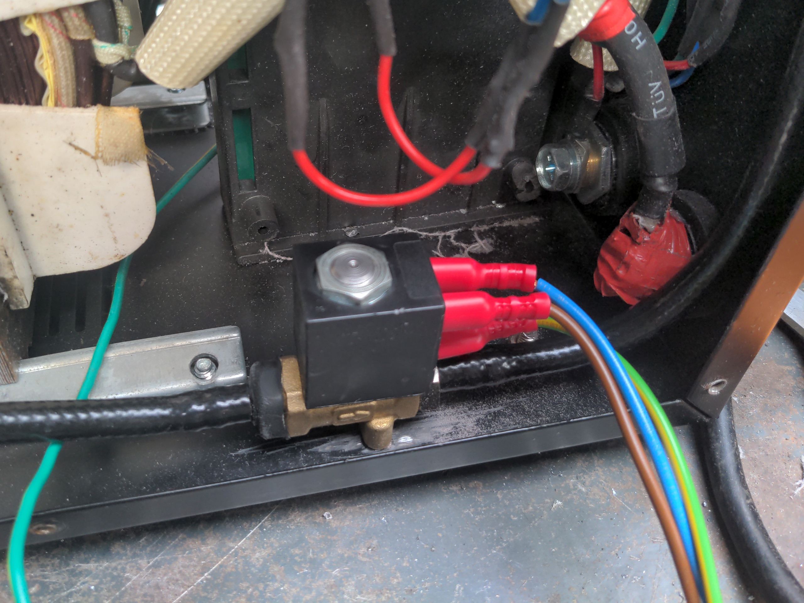
So first, remove both side panels from your machine. Then let's get the solenoid mounted in the machine. The picture above gives away what I think is the best location for it to be mounted. This means drilling two 4mm holes into the bottom of your machine and screwing it in with two tiny M4 bolts. Easy. Just don't forget that the solenoid only works in one direction; an arrow on the body indicates which direction the gas should be flowing.
At this point you may as well attach your gas hose from the outlet of the solenoid to your Euro torch socket. How you route this is up to you; you'll need to drill a hole in the top deck of the machine, add a grommet, and feed the hose through that. On this section of the gas feed, cable ties work fine for attaching the hose to the barbed fitting. That's because the gas will always choose the easiest route to escape, and that route will always be through your welding torch. You'll never have enough pressure here to blow the hose off the fittings, because it'll find its way out of the tip of your torch instead.
Next you will want to attach a small ring connector to the yellow and green wire and attach that to an earthing point in your machine. You can find one of these by seeing where the other yellow-and-green wires inside the machine go to. Also easy. There's actually more than one of these points to choose from; I recommend that you do not use one of the earthing points on the removable side panels on your machine.
Next you will want to bring the other two wires over to the other side of your machine, cut them a little longer than you need them to reach the main PCB, and attach a 6.3mm piggyback spade connector to your blue (neutral) wire and another to your brown (live) wire.
Let's take a look at the main PCB.
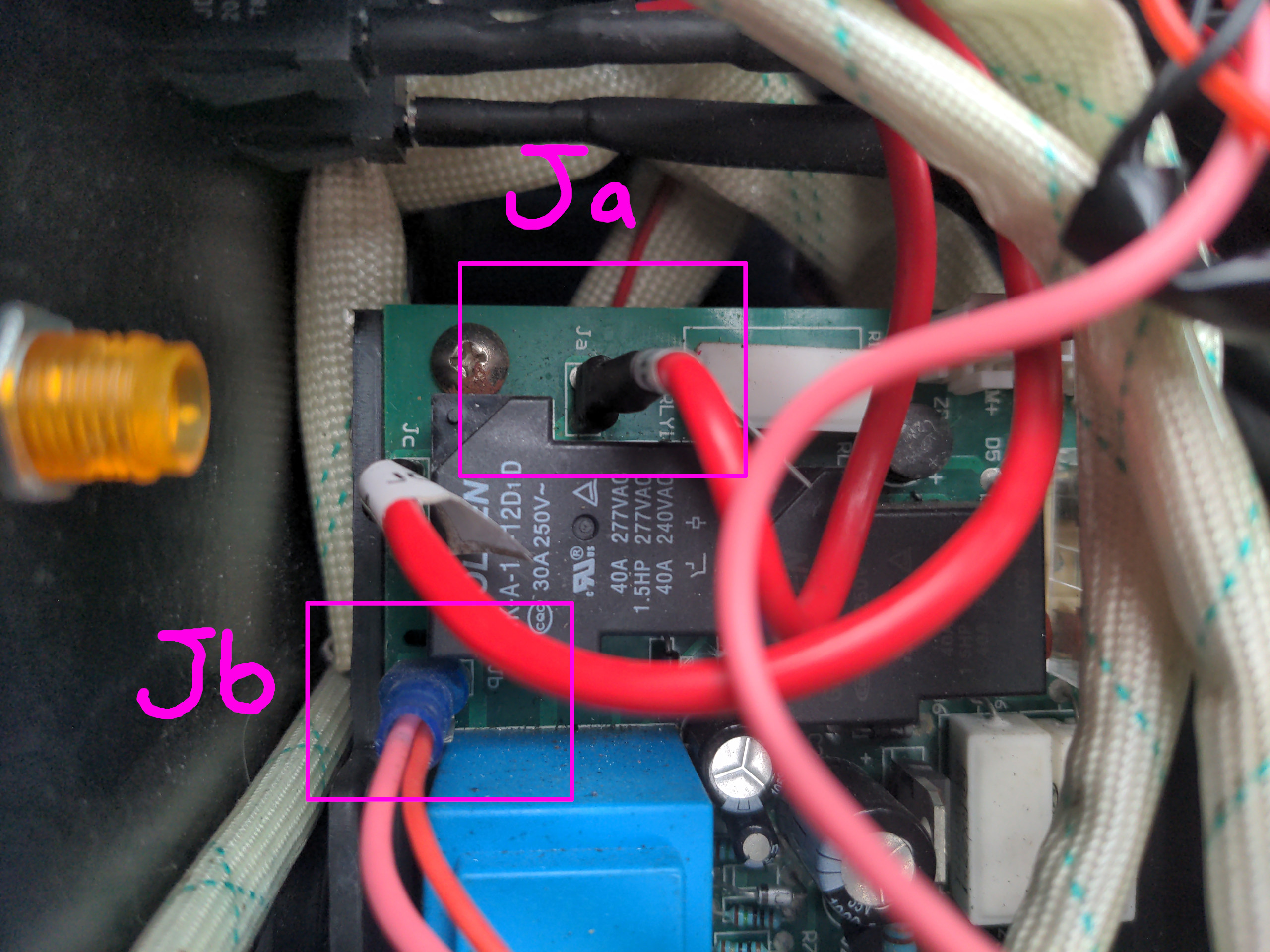
But before I say anything else: IF YOU ARE DOING THIS CONVERSION ON ANYTHING OTHER THAN THIS EXACT MACHINE THE TERMINALS ARE GOING TO BE DIFFERENT. Pardon the all-caps and bold. You probably won't die if you get this wrong, but don't take the risk of having a bad day. Don't assume that a board that looks something like my one will be wired the same. Test it yourself with a multimeter; you should read a minimal AC voltage (never zero because of circuit leakage) between the two points when you're not pressing the trigger, and somewhere around 250 volts when you are.
First, pull off the spade connector marked both in my picture and on the board as Ja. This should be tight; you might need a small flat-blade screwdriver to assist you.
Attach this to the piggyback connector you crimped on to the brown wire from the solenoid.
Make sure it is still nice and tight; if it feels loose, remove it, squish the spade connector a little with some pliers, and re-attach it.
Now attach your piggyback connector to Ja on the board.
Repeat this procedure for the blue wire and Jb on the board; pull off the plug, attach to the piggyback connector, put piggyback connector to Jb, also checking for tightness.
If your board is not the same as mine, and you aren't feeling confident, buy a kit from a company that will support you with installing it. The ones from Yorweld Supplies in the UK will come with a piece of paper with an email address and a phone number; send him photos of the board and he'll tell you how to connect it. (I know he actually answers these emails, too.)
Anyway, on this particular machine, you should now have a working gas solenoid. You can do your initial validation of this by turning the machine on, pulling the trigger on your torch and listen for the solenoid clicking.
That isn't the same as it being wired up properly. Ask me how I know! But it's a good sign that things aren't completely wrong.
How do you know?
...you then asked so conveniently for my narrative. Well, the first time I did this I went in with some flawed logic and attached the neutral to Jc on the board.
I heard the solenoid click when I pressed the trigger and figured "well that works".
What I had actually set up, though, was a situation where the solenoid was open normally (feeding gas into the torch) and closed (not feeding gas into the torch) when I pulled the trigger.
That's when I had to reach out to Yorweld Supplies, who told me to put neutral to Jc.
This surprised me, because I assumed that point on the board was only for control of the overheating warning light.
Anyway, on top of the "does it click" test, you might want to do "does it not click when I turn off power to the machine". It should not click when you turn off the power, because that suggests that its default state is electrically-controlled, i.e. it's default-open.
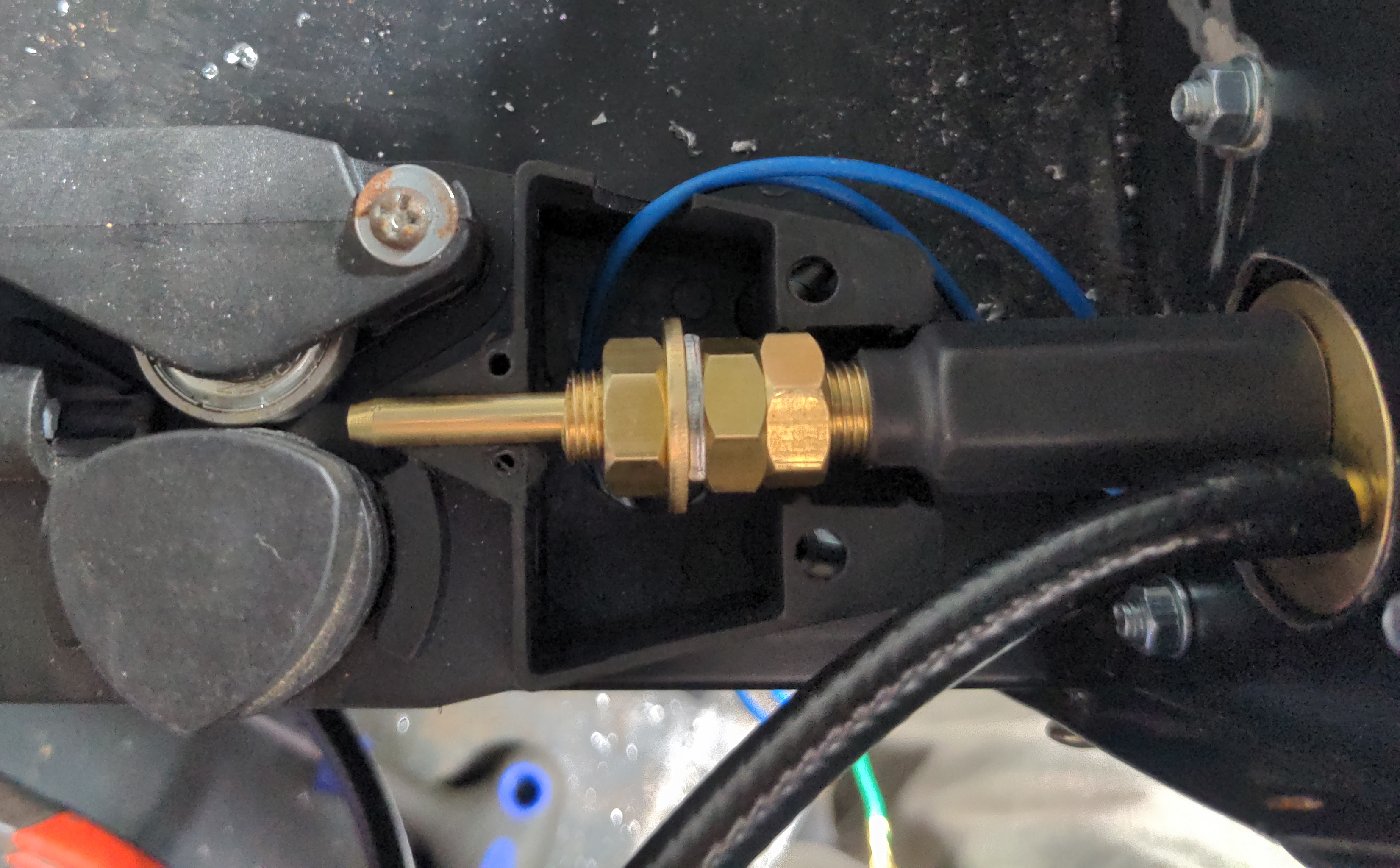
Finally, you want to connect your gas bottle to the inlet of the solenoid. To keep this neat, I decided to feed this out of the back through a bulkhead fitting.
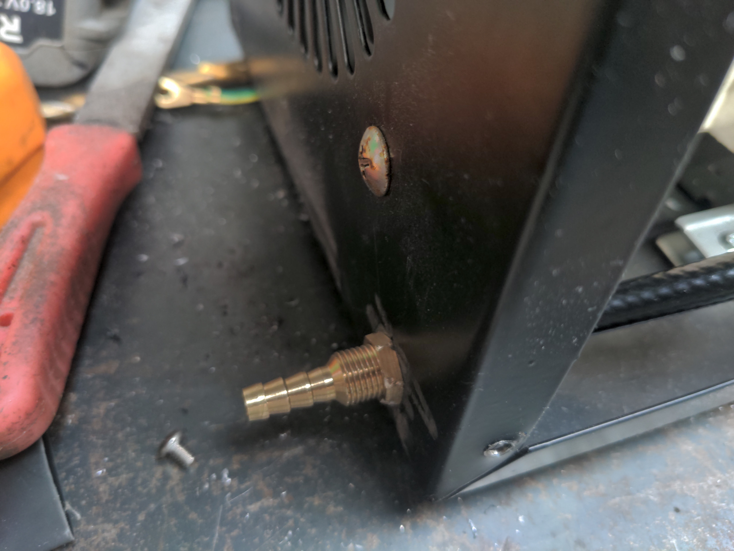
That only added a couple of quid to the costs; you can let the gas hose out the back via a hole and a grommet if you like.
Finally, turn the gas on, and test if the welder works as you would expect it to.
And well, that's where my one failed; after some debugging it seems I had a bad welder all along. Oh well! So this machine has been stripped for spares, and the Euro torch conversion is going to go on a cheap used machine I got on eBay.
Still, I'm glad I had the chance to play with the internals of a welder. They're much less of a black box to me now than they were when I started. And hopefully I've thrown something out there which will help someone else be a bit more bold with theirs.
See you next time.