A couple of odds and ends for the Rover P5's rear-mounted radiator
So I mounted a radiator in the wrong end of a Rover P5. That left a couple of things to deal with before I got sidetracked onto mountain bikes for some months. Actually, there are at least six things to deal with, but a couple of them which I felt like dealing with at the time. I do things in the order I feel like doing them; that's what keeps the motivation high.
Vents
The first was ventilating the boot lid. It was partly because I did not want hot air to pool there when the fans are off, and it was partly so I had more assurance that there was enough air for the fans to pull from when they were running. That meant boot vents, and that also means you should look away now if you are sensitive about seeing perfectly good classic car panels having holes cut into them.
There are no vents available off the shelf that would look right on this car, and which would conform to its curves. That meant I had to make some. Making them myself gave me total freedom to decide on their size and shape, so here's a perfectly good classic car panel with some massive holes cut into it.
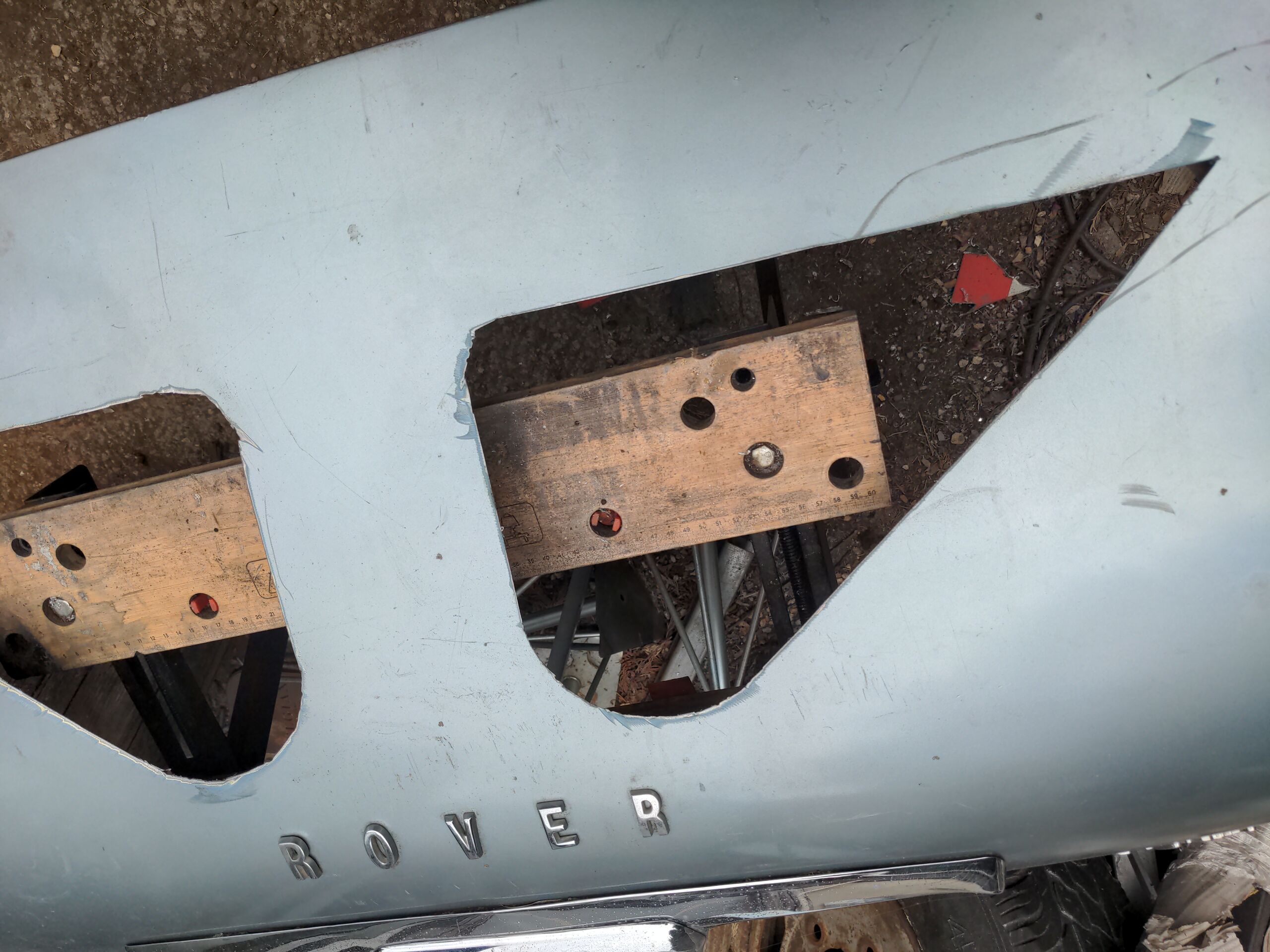
I warned you!
These are ideal places to put boot vents. They do not require cutting through the structural frame of the boot, so they're not going to make the boot all floppy and weird like a pro drift car. You can see what I mean if you look at the underside; I've marked one of the hole areas for clarity.

They're also big, which means lots of air will go through them. And they are nearly at the highest point of the boot area. Hot air will naturally want to rise, and so it will ventilate itself out through the vent and not allow hot air pockets to form. In theory!
Of course I'm not just going to have holes there. I had a design for a vent in my head, but to validate it I made a crude version of it from cardboard...
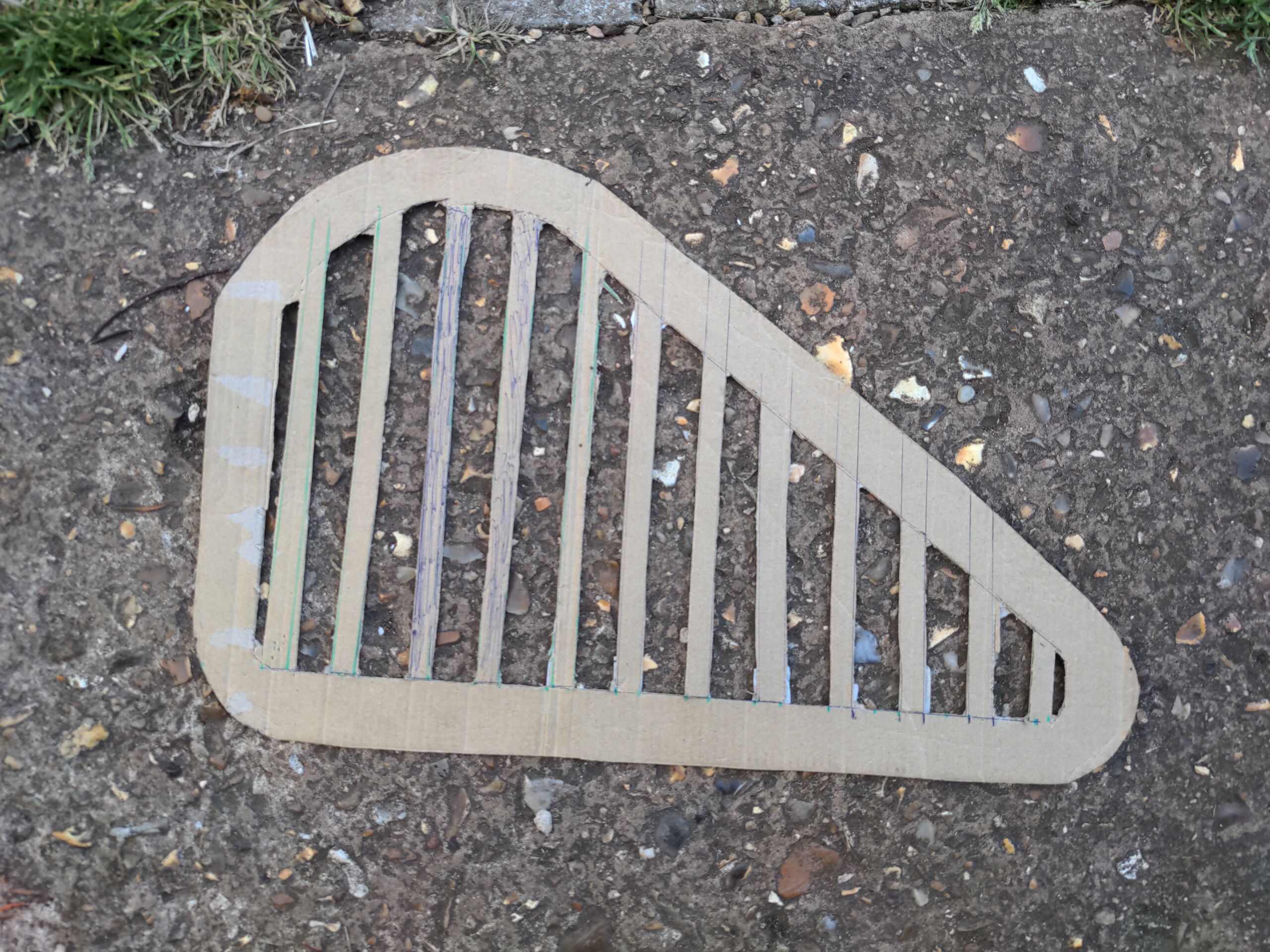
...said "sick, fam", and then got to work.
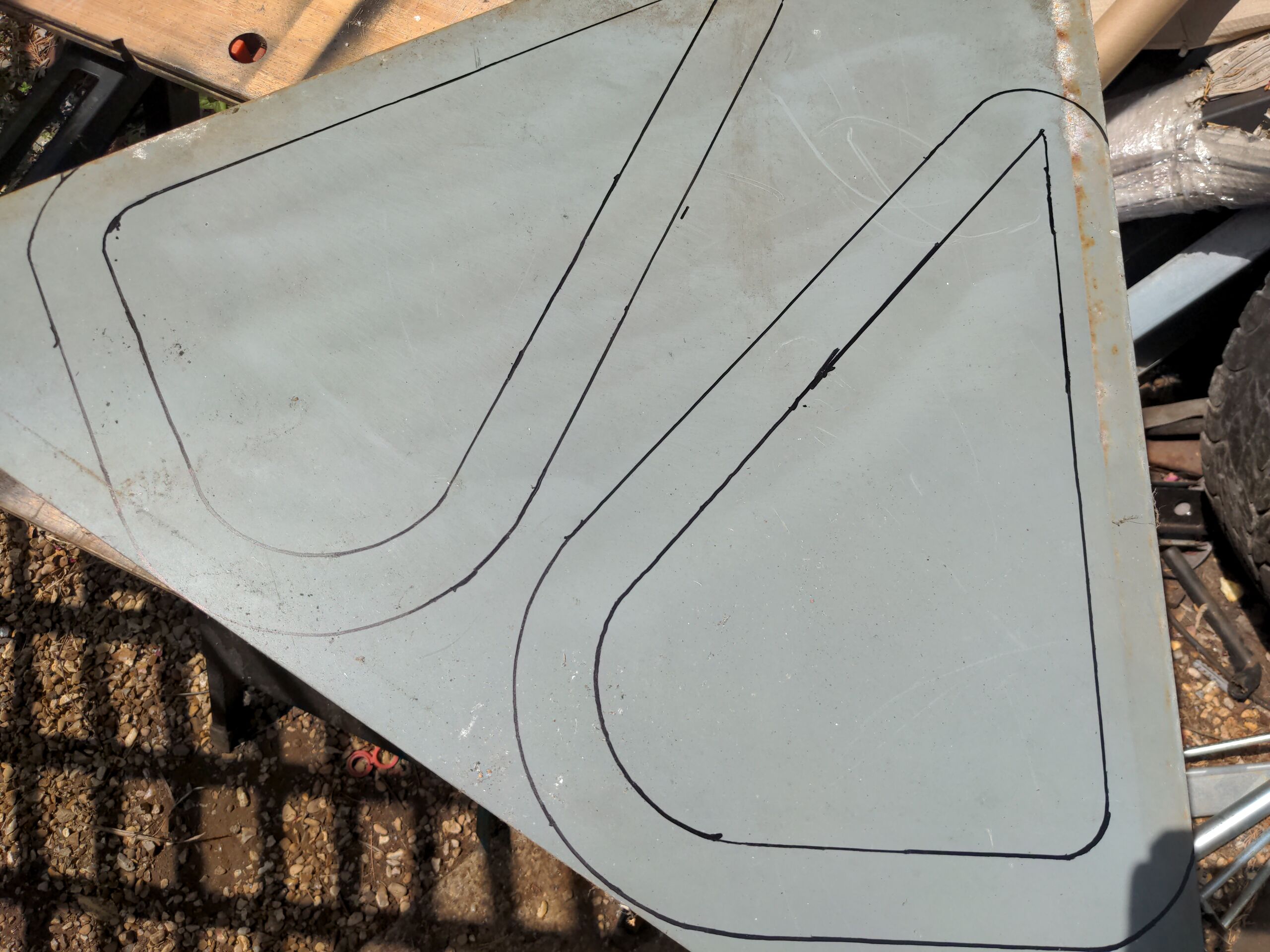
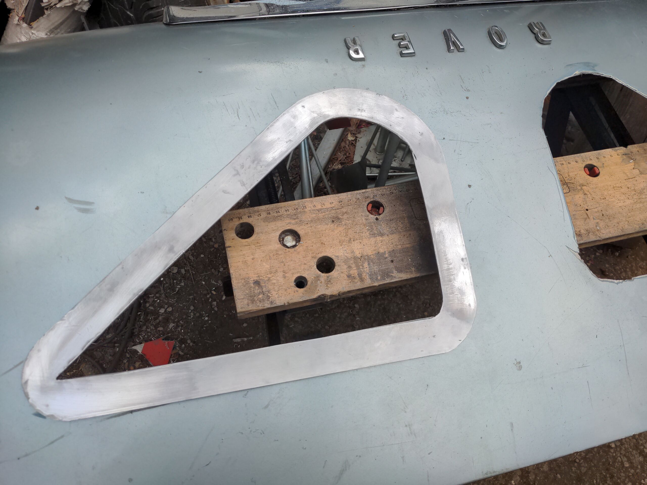
I made the outside part out of aluminium. I used a road sign which was rescued from a skip. It's made of an interesting lightweight alloy and it was also free.
In between these, I cut and glued small lengths of ABS plastic hollow square tube, spaced at regular intervals.
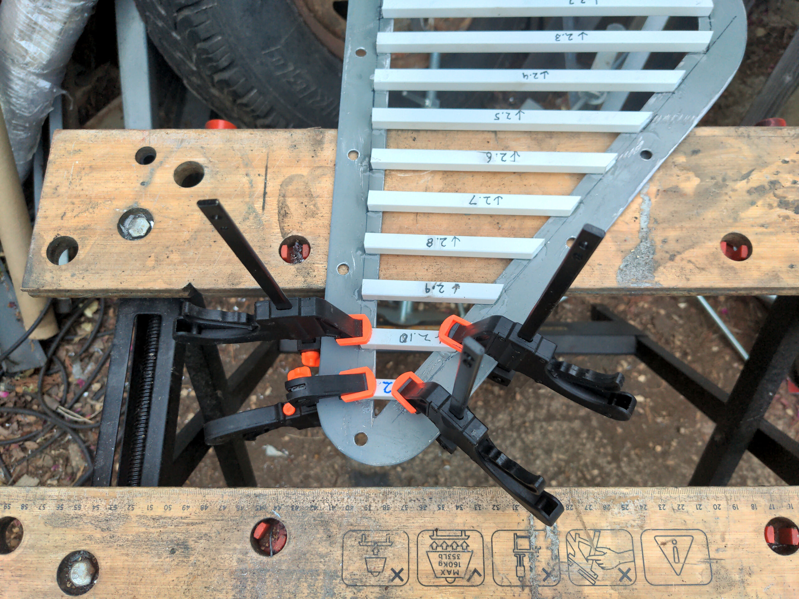
I initially glued these in with epoxy, but that was not sufficient to hold some of them. Some of them were fine, for reasons I don't understand. I switched to VM100 for the ones that could easily be pushed off.
With the aluminium polished, the slats painted black, everything clear-coated, and fitted with stainless hardware they look like this.
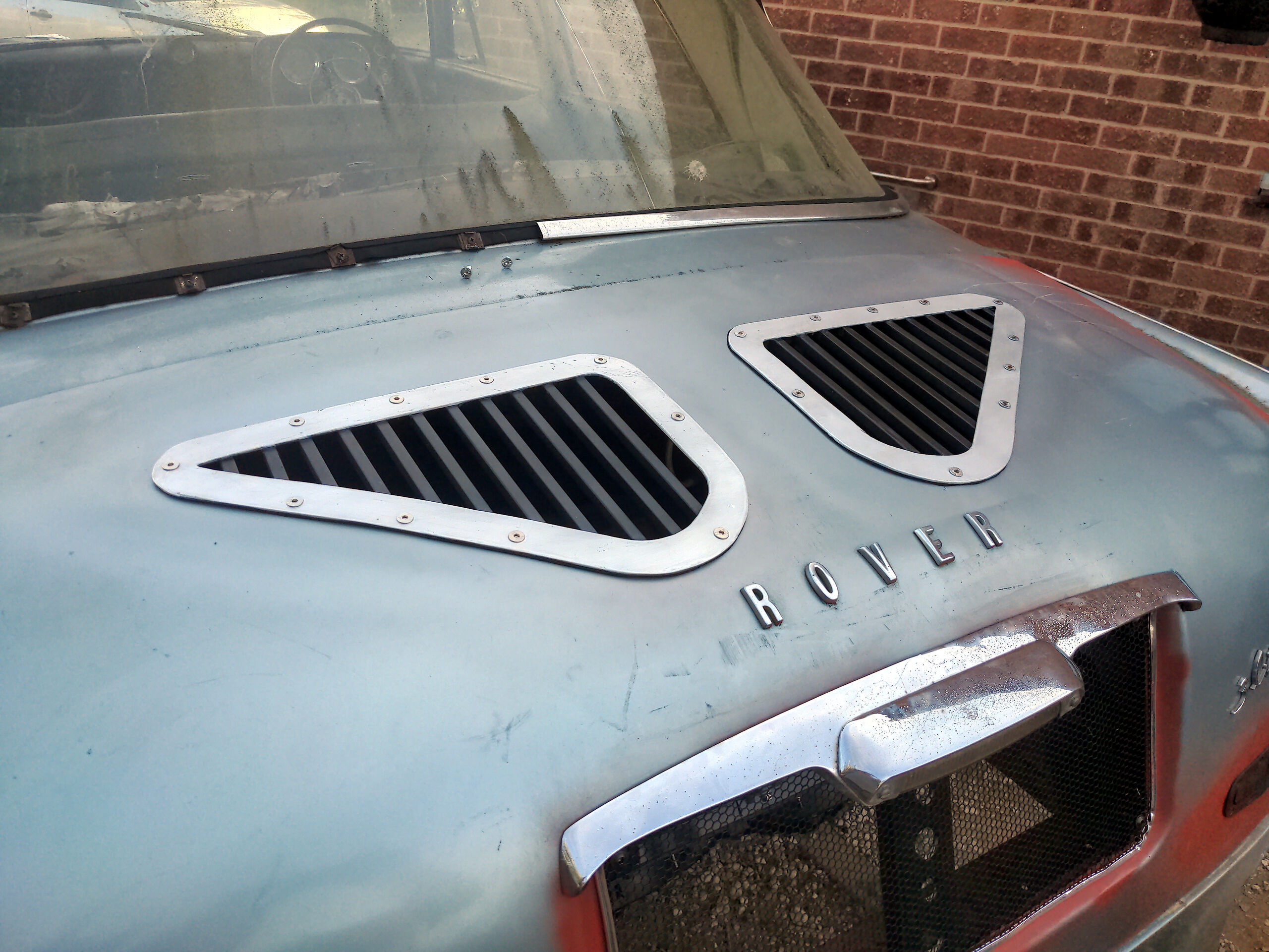
Ten foot good! I might end up doing these body-coloured though.
I know what you're thinking. It's something like "these are going to allow rain water into the boot". And you're right; two massive holes in the boot lid will in fact do that. But the idea of the boot area being watertight went out the window when I decided to make a massive hole in the boot floor for the radiator to poke through. The boot must be waterproofed and drained; two more holes will not hurt.
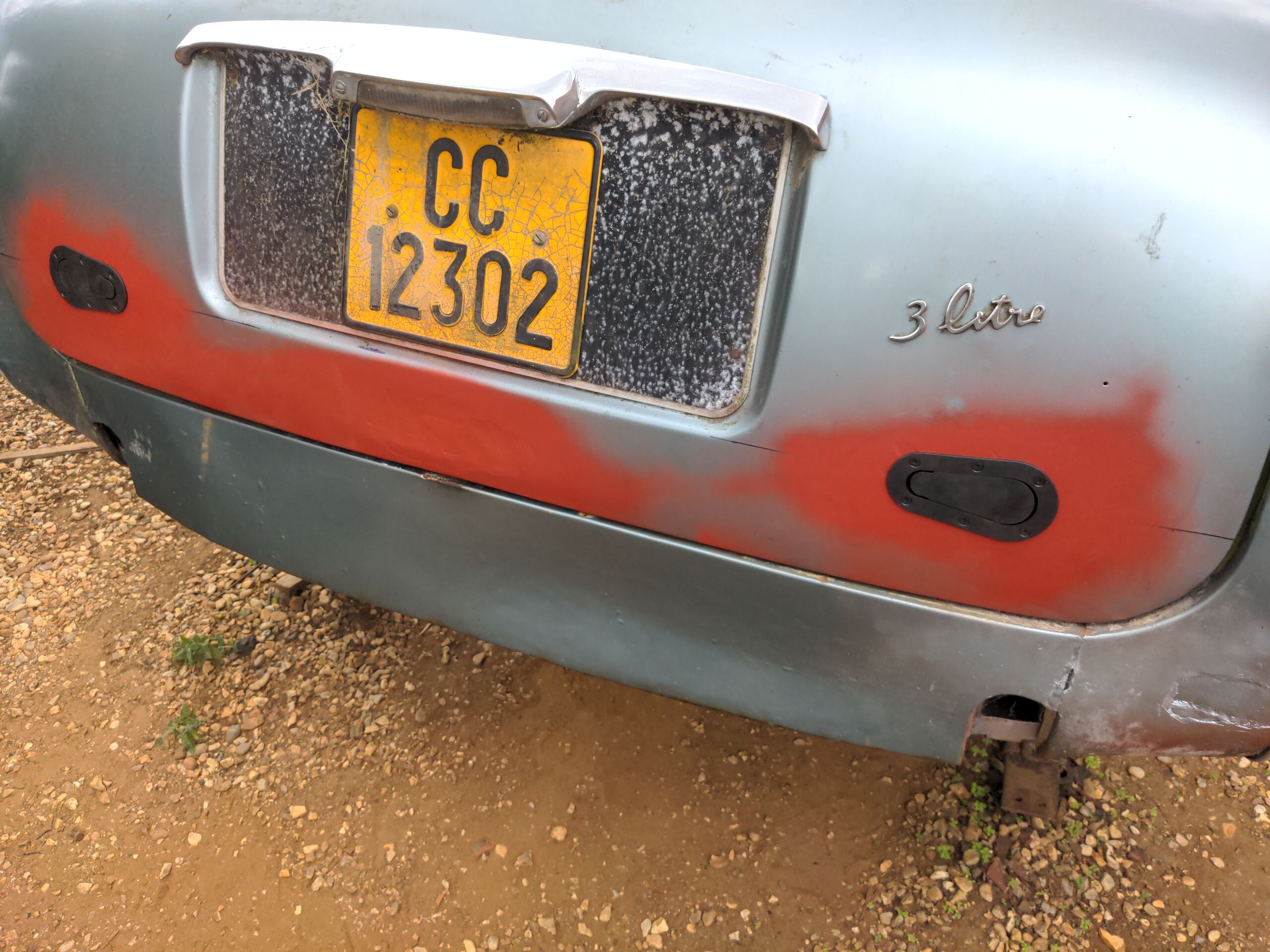
But wait, there's more (holes). If you look closely at the picture above, you'll see that there are actually three massive holes now. The area where the number plate was is also one big vent. I did this partly because these huge horrible bolts for the number plate surround kept poking me in the head while I was working inside the boot, and I wanted revenge on them, or at least to never see them again.
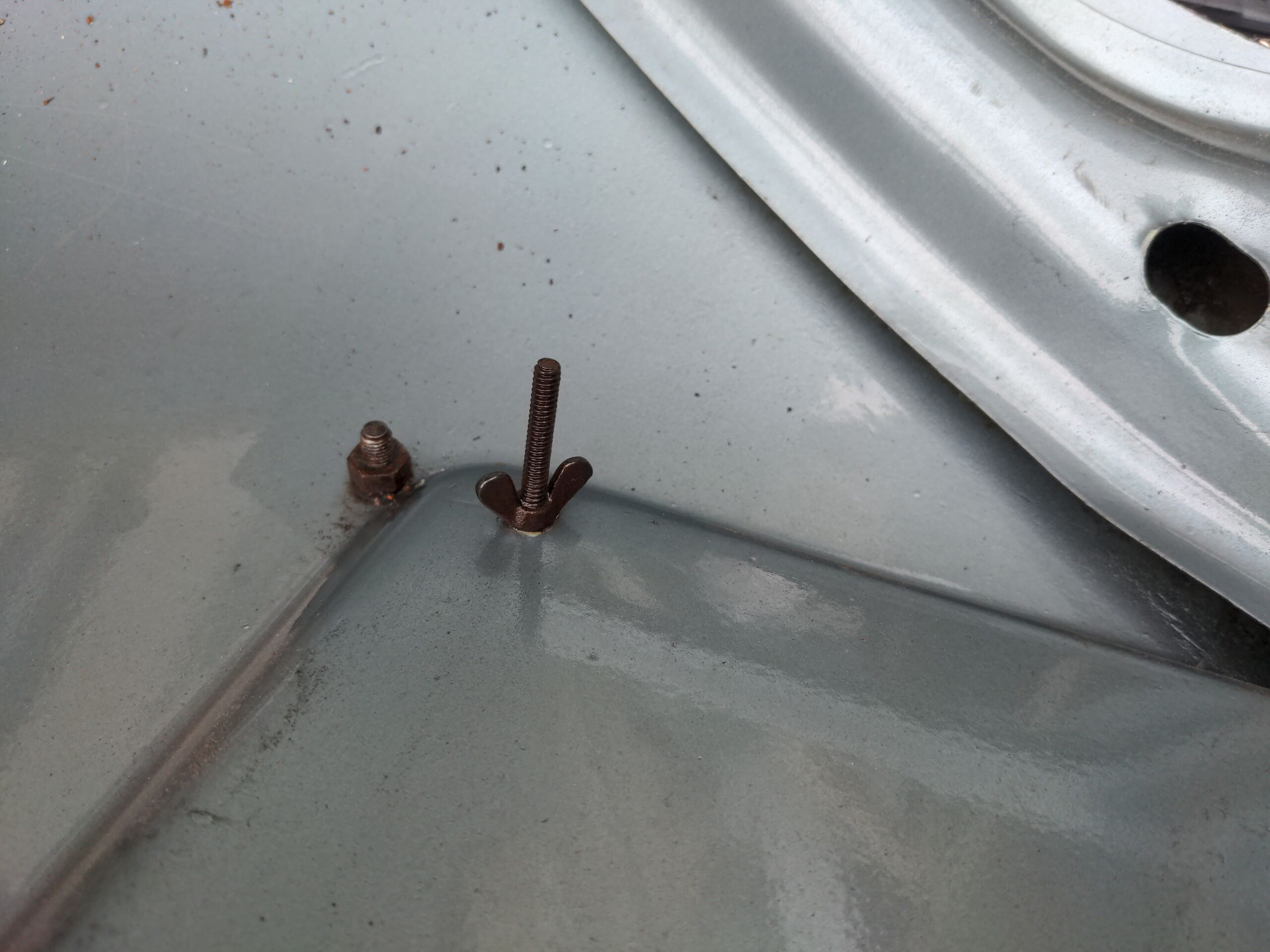
But it was also because I wanted to promote air flow, from under the chassis over the radiator to the rear of the car. You can see better what's happened here in the pic before I tidied everything up.
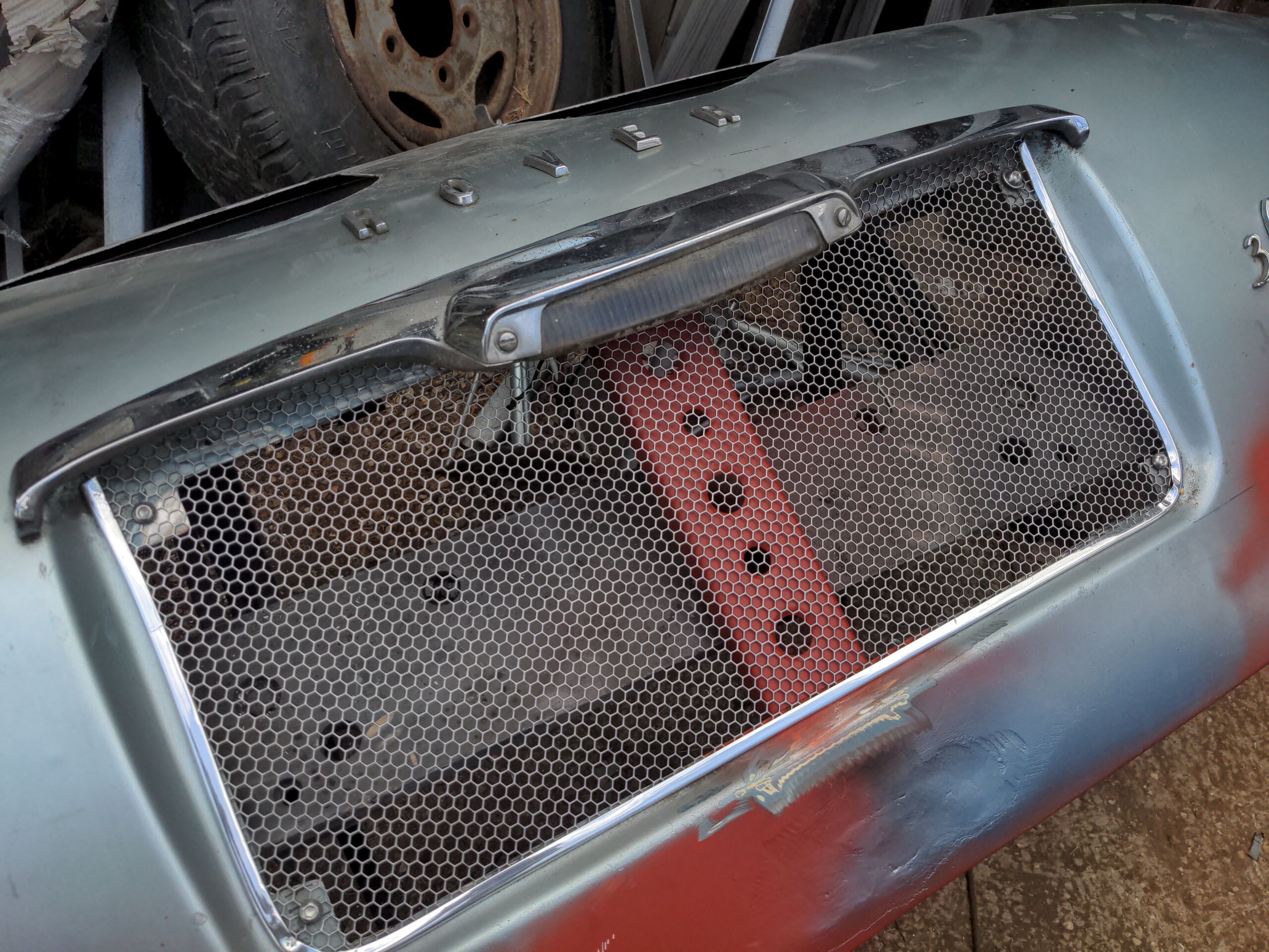
This entire area has been replaced by bolt-on mesh, and I've welded in a piece of dimpled steel in the centre to restore the strength to the boot lid. Much of that extra ventilation area will be lost when I fit a number plate here, but not all of it.
But wait, there's more! Look again and you'll see...
Aerocatches
I decided to fit Aerocatches to the boot lid, because race car. They replace the original boot catch. (I did this before any of the things above; it's why there's no massive holes in the pic below.)
If you're familiar with how Aerocatches are normally used, you'll be wondering how I have these mounted on a vertically-lifting panel like this. I've seen Internet people wondering about this, with some asserting that it is not possible, which it is. The answer is actually in the Aerocatch manual under "Hinged panel mounting". Once they're fitted to your panel, just cut out this little tab on the bottom of the Aerocatch.
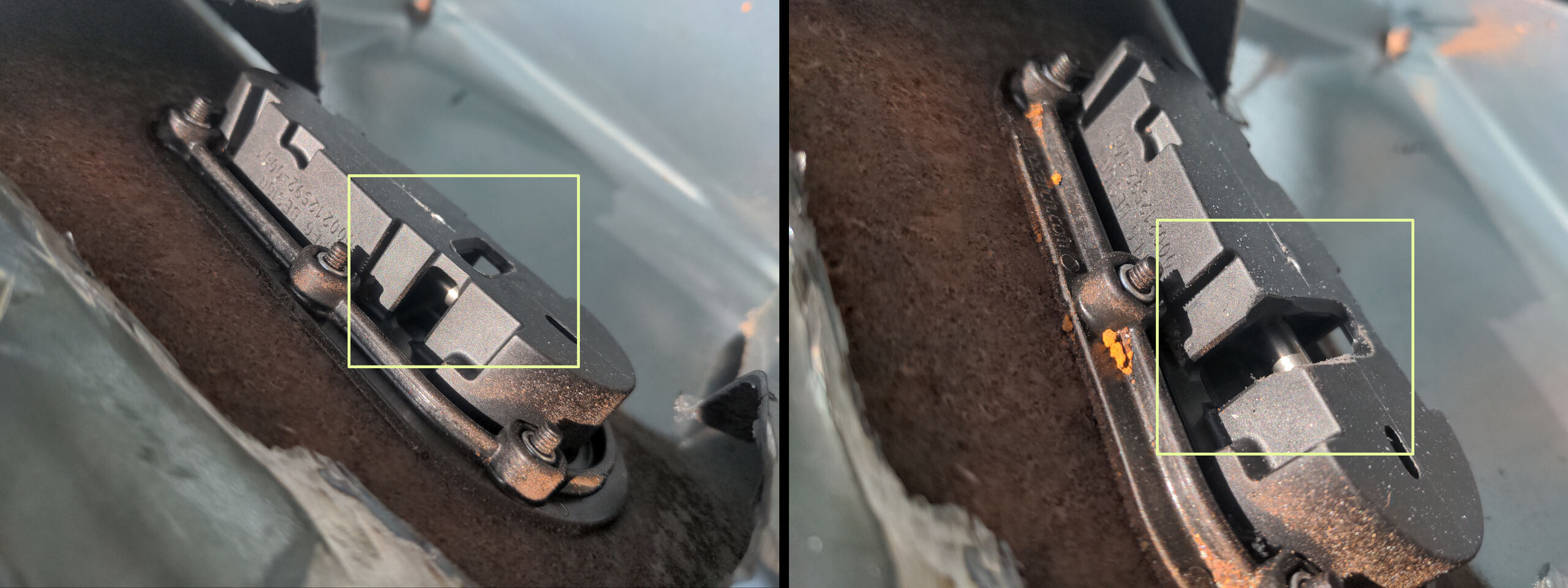
That'll allow the strike stud to slide in from underneath. I mounted the strike stud on a short length of angle iron with a slot cut into it. It's crude, but it works.
That makes the original boot catch redundant. I could have kept it for cosmetic purposes. Instead, I made a little steel blanking piece and welded it in.
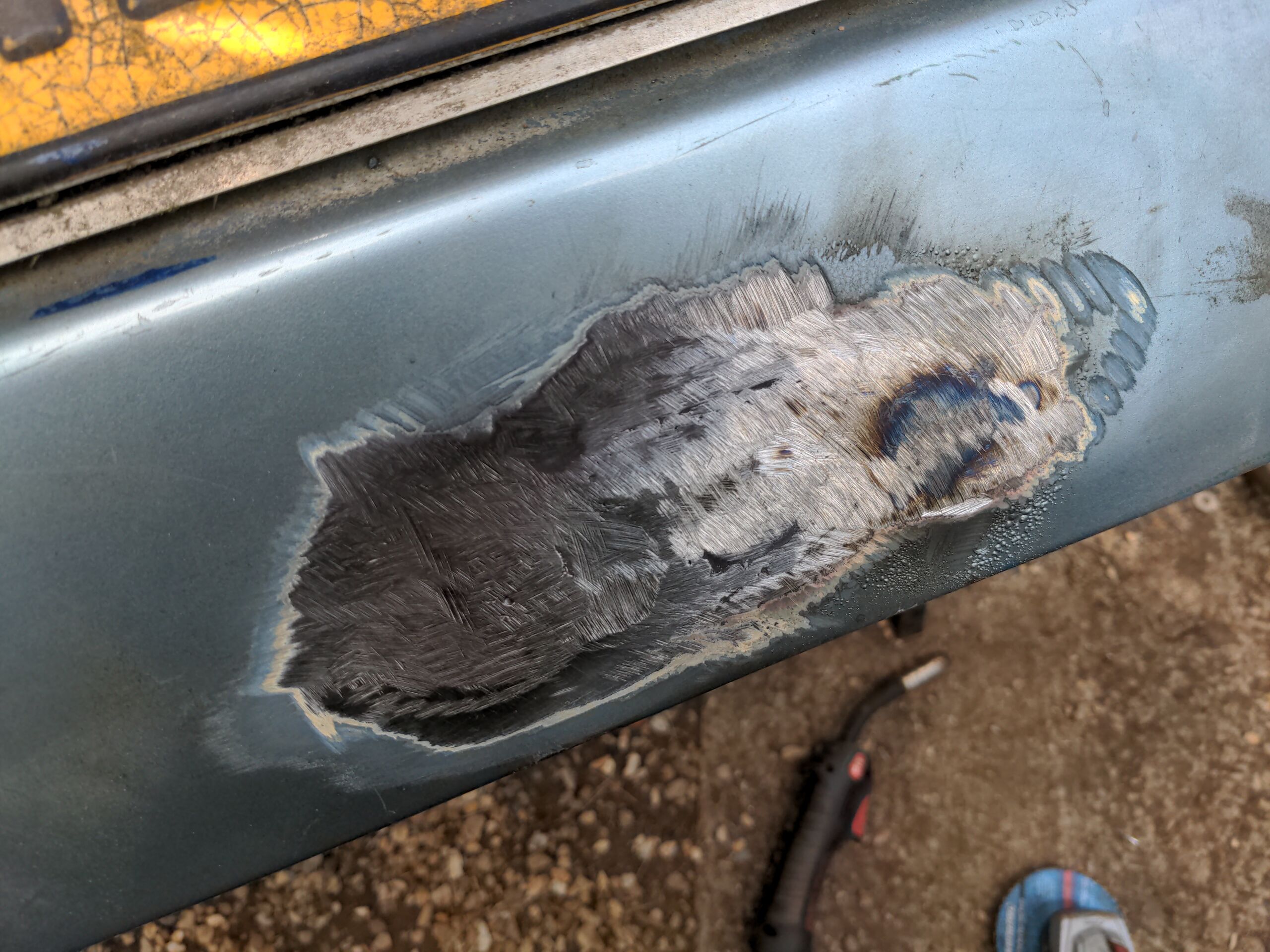
That's alright for now; it'll get smoothed out whenever the time comes to fix the bodywork on this car.
Mounting an expansion tank
I bought CNC'd Radium expansion tank. It's very fancy.
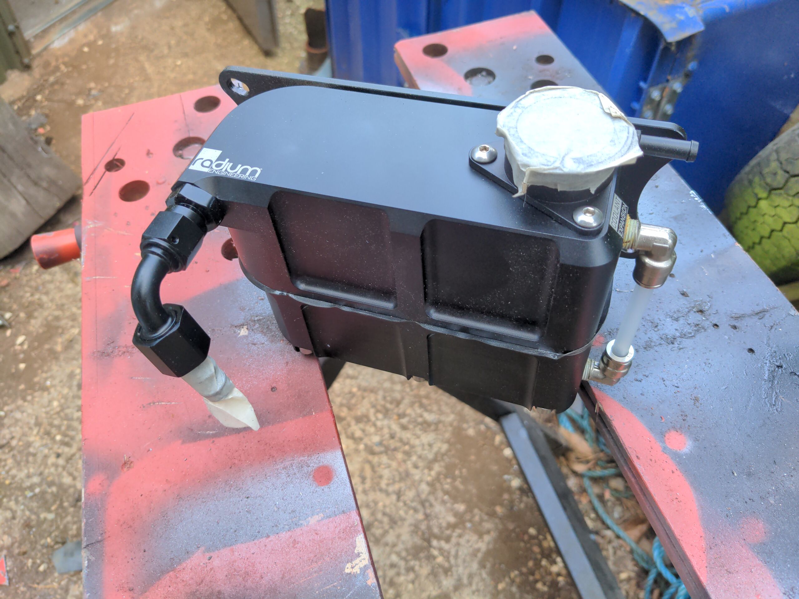
An expansion tank is necessary on a rear-mount radiator setup because the radiator is almost never the highest point of the pressurised cooling system. One of the things an expansion tank does is to relocate the radiator cap such that you can bleed the system. Actually, it's necessary on the Sierra Cosworth which my radiator is made for, and necessary on a lot of modern cars too; having an expansion tank gives a car's designers more freedom to place the radiator where they want it to be, rather than where it must be.
Let's look at where we can mount it.

What I'd really like to do is mount it outboard at point A, somewhere on the inner ring; it'd make the bracket simple. I don't have that option, because there's no point in that area which will make every part of the expansion tank higher than the radiator and clear the boot hinge. That left B, but I still wasn't happy with that. Ideally, I want the expansion tank as near as possible to the highest point of the radiator to keep the path to the expansion tank as simple as possible; B on the left-right axis, but A on the front-rear axis.
That'll need the mother of all brackets, which would actually be more like a tree. Because I bought the absolute fanciest billet CNC expansion tank imaginable, it would only be fitting that the starting point of my tree is some random shit bit of steel which my brother saved from a skip. I swear bro it'll look sweet bro
A little imagination and about a day later...

See, you should have trusted me! It has captive bolts for mounting the expansion tank; it makes assembly and disassembly easier. And the dimples and returns allow me to use much thinner steel than would ordinarily be necessary.
That got welded onto a section of gusseted and dimpled 50x50x2mm angle section.

That's my second attempt at the upright. The first attempt was with 1mm thick angle section. That turned out to be too thin. The problem was not that it flexed; the problem was that it oscillated after flexing. I did not much want to find out what effects that would have on the bracket, the cooling system or the rest of the car when that happened in actual use.
I also made a mount for an overflow tank. An overflow tank isn't strictly required, but it is polite; if I overheat the car I would like the coolant to be captured, rather than dumped on the floor.

That's just another random piece of steel offcut made into something else. It doesn't need to be that shape, but I liked that shape. That one has captive nuts instead of bolts; the shape of the overflow tank I picked would make assembly with captive bolts awkward. If I was doing this again I'd probably have only done two dimples, because I'm not a fan of the spacing here, but I won't.
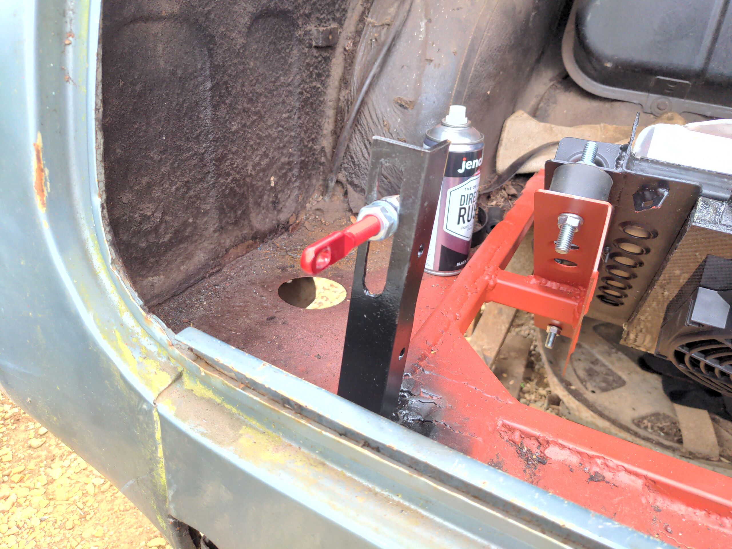
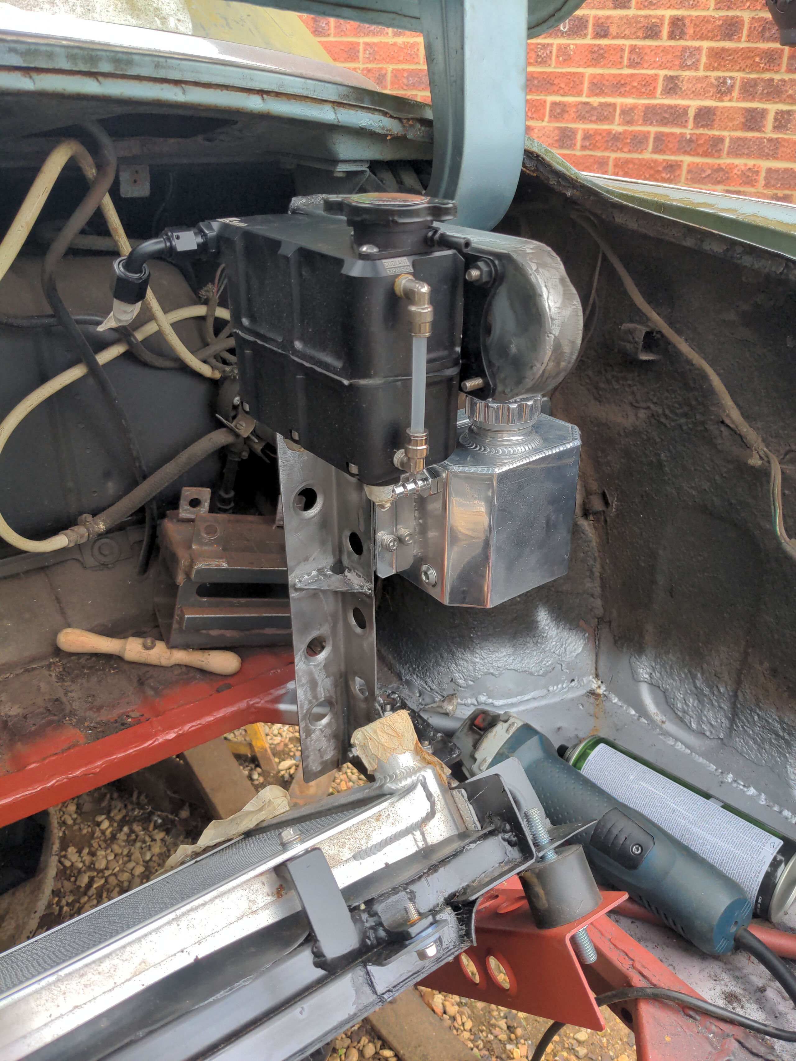
Before committing any further I did a dry run, clamping the bracket to the reinforcement frame I made around the hole where the radiator goes.
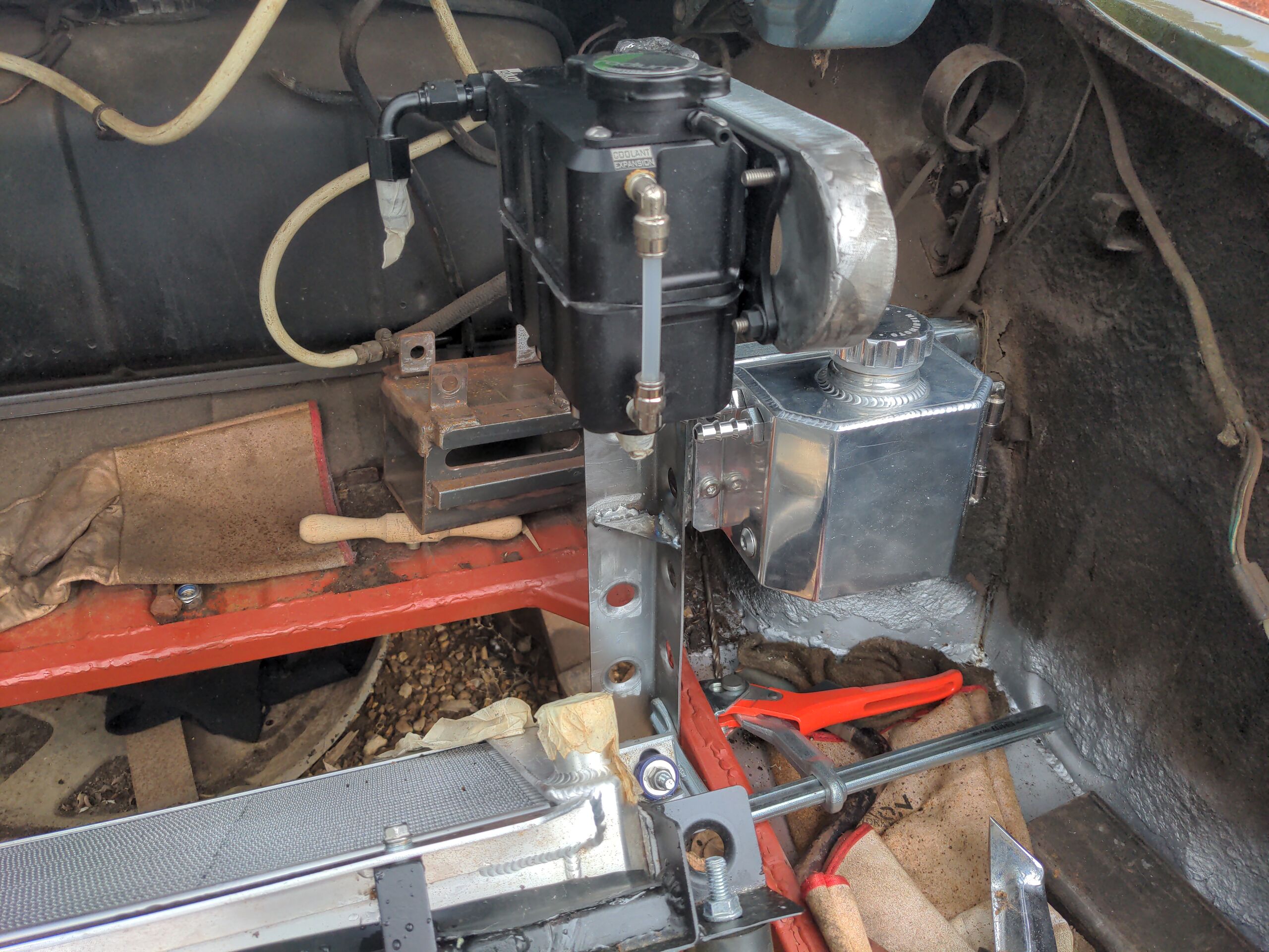
You can see the polished Mishimoto overflow tank which I forgot to take any other pictures of. It looks far nicer than it has any right to be at the price it sells for.
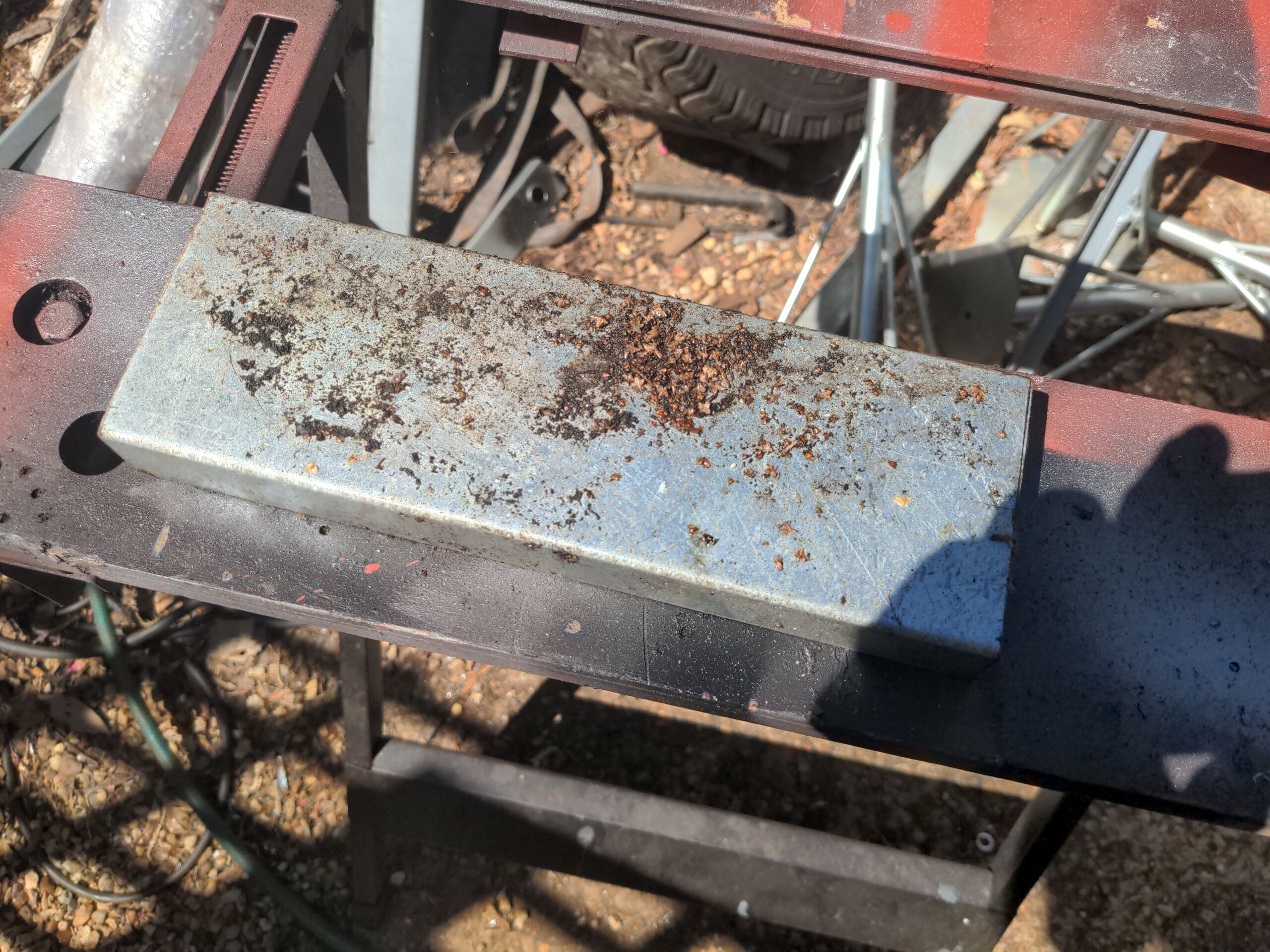
I was happy with that, so that meant I could commit to it. I wanted this bracket to be removable. Making it removable means having somewhere for it to bolt to, and that is a massive thick piece of angle iron with four captive bolts welded into it.

That got welded on to the frame surrounding the rear-mount radiator.
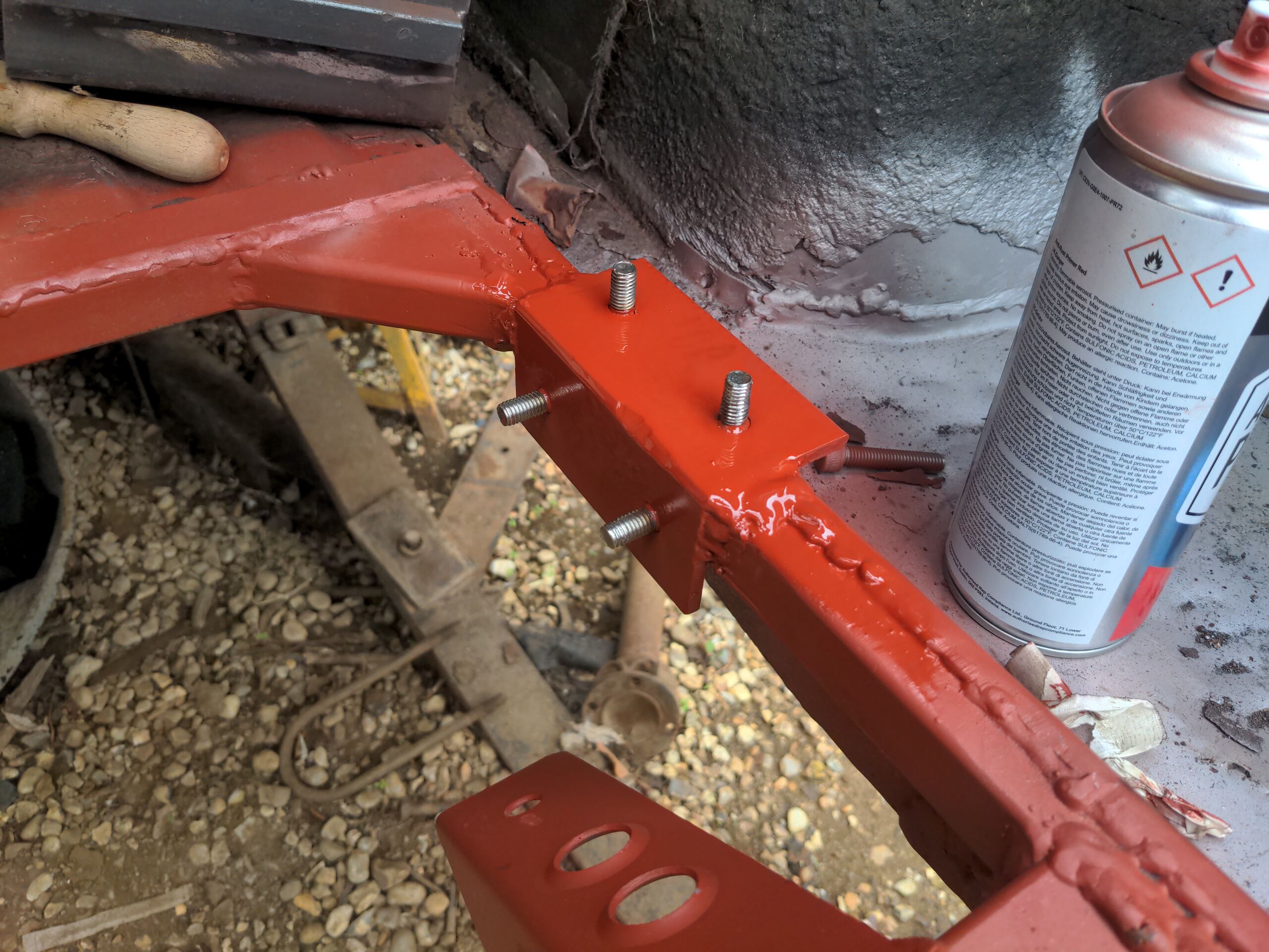
And if you were wondering how any single assembly could attach to captive bolts at right angles to each other, the answer is slots.
:)
I did one last all-up test to ensure that this was all sensible; I mostly wanted to ensure that no compounding errors had caused this to be at angles things should not be at. It was close enough.
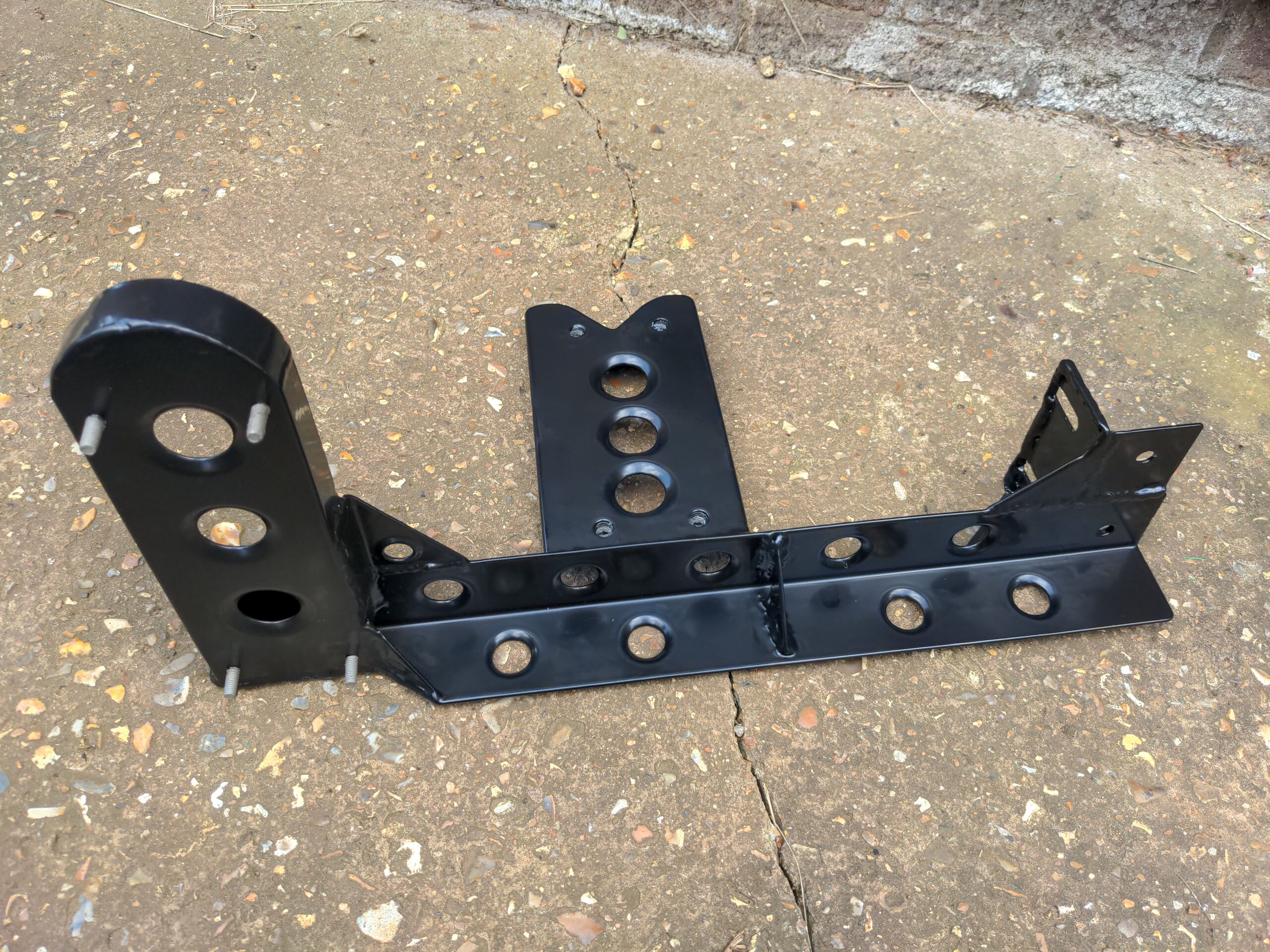
Which meant that I could take the bracket/tree down the road to the powder coater, and a few days later it came back looking awesome.
See you next time :)