Rationalising the 323 GTX, part 6: the turbo
This was my turbo.
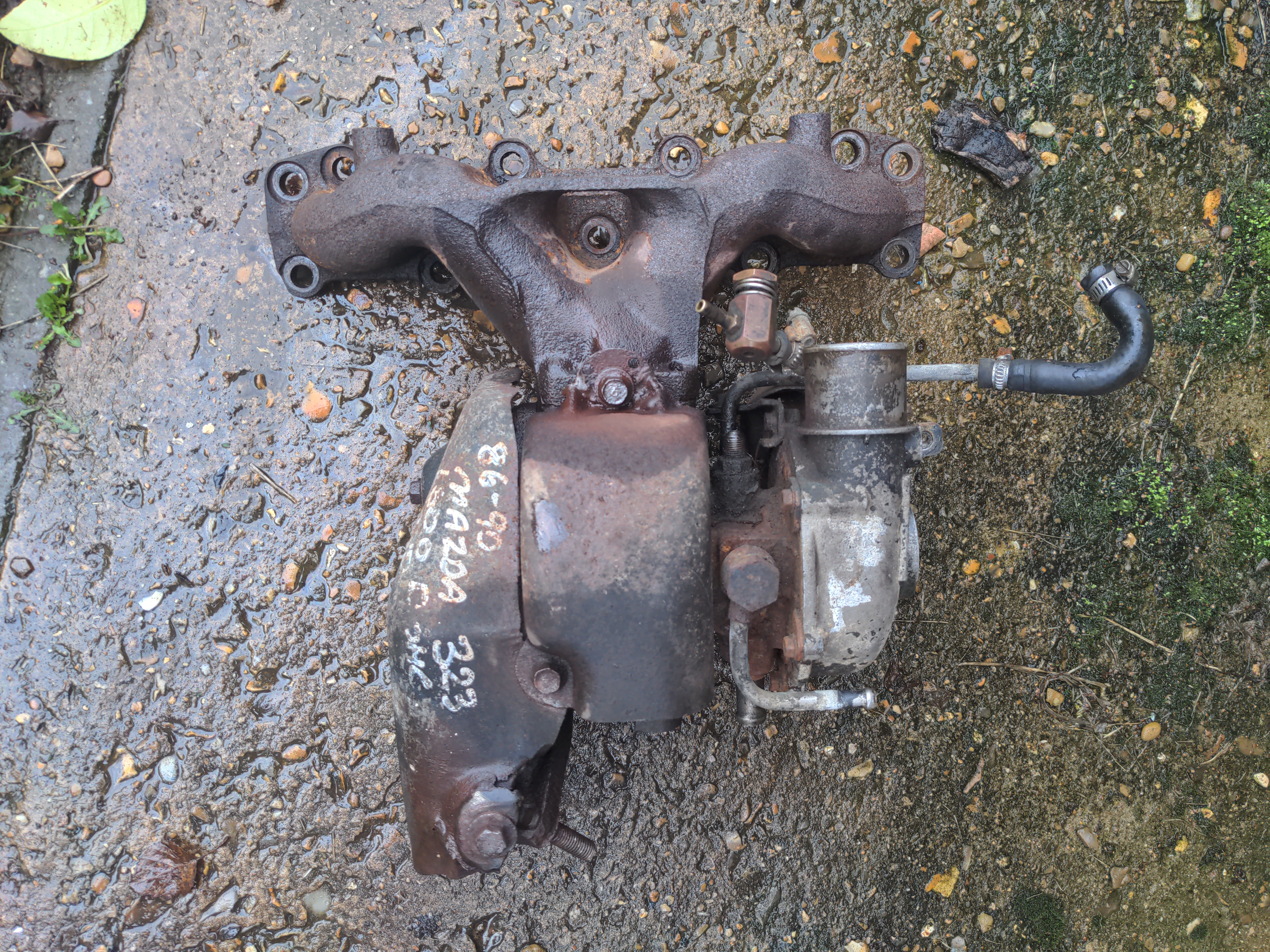
It is an IHI VJ9, and it is also ancient worn-out junk that cannot be fixed.
The VJ9 is a tiny turbocharger built on the IHI RHB5 frame. Despite its size, it is ridiculously laggy compared to a modern turbo of the same size. I came to love that in the few months I had it on the road; a mildly-lively 16v engine that transforms violently into a howling turbocharged rally car engine at about 3500 RPM is hilarious.
This is actually the second turbo that has been fitted to this car. Back when my brother owned my 323 GTX, the original turbo was so worn out that the car spewed enough white smoke to be an actual danger to other road users, so he used his superpower of finding car parts that do not exist to acquire a "good" spare.
"Good" is in quotes, because it was still worn out; there was slack in the shaft, just not a quarter-inch of it like the old one, and the car did not spew smoke after the turbo was swapped. It was sure to be another failure in the near future, and re-fitting this to a freshly-rebuilt engine seemed insane to me.
As I found out, replacing or rebuilding this turbo has some pitfalls: there are no replacement VJ9s, there are no spare parts, and nobody will work on them.
1. There are no replacement IHI VJ9s.
They're gone; as far as I know they were only fitted to the Mazda 323 GTX, and only outside of the US. US models of the GTX had a slightly different VJ14 on the same RHB5 frame; the US models of the GTX made somewhat less power, so I shall assume the US turbo is worse. Occasionally one spots a used VJ14 out there, but that might well be a worse turbo than the VJ9 and there's no guarantee that it would have been a straight fit anyway.
The obvious answer is to have my current turbo rebuilt, which brings us to...
2. There are no spare parts.
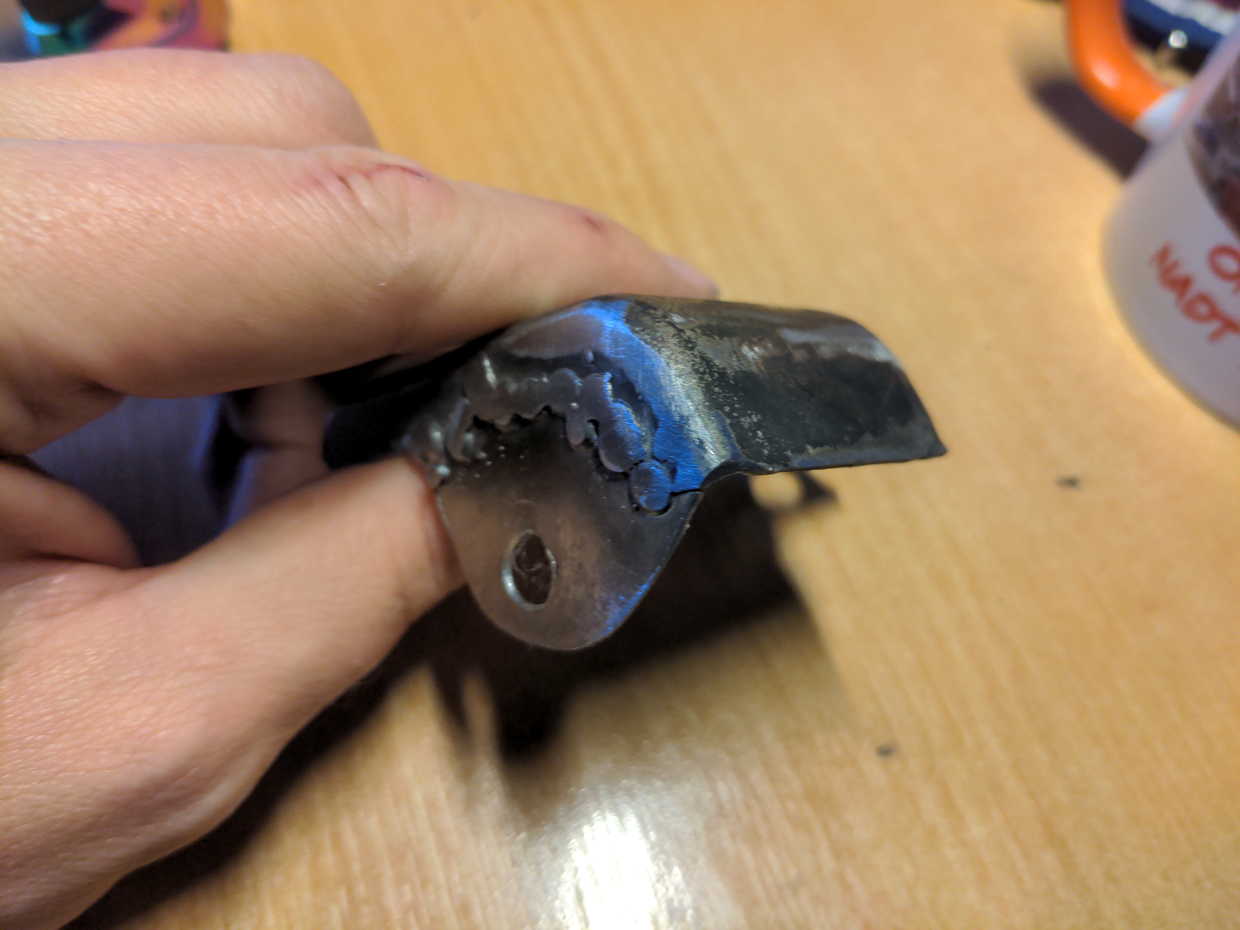
I shipped my turbo to who I consider the best turbo company in the country - for turbos that are not obscure ones fitted to extremely obscure cars, anyway. The report back was that the turbo was actually completely shagged:
The bearing housing has damaged ring lands and the actual internal sleeve has separated – not reusable.
Turbine shaft has heavy journal wear – not reusable.
Seal plate has excessive ring land damage – not reusable.
Turbine housing has multiple cracks around the wastegate seat and volute – will go again with some processing.
Compressor housing has rub damage – will go again with some processing.
...and as I soon found out, none of the parts required exist anywhere; there was a multi-month delay getting my turbo back while aforementioned best-in-the-country turbo company scoured all their sources for some stash of parts that we all hoped existed, and did not exist.
3. Nobody will work on them
I know; I've tried. Any company in this country whose website claims they will rebuild a VJ9 will not actually rebuild a VJ9, and I know this because I have called all of them. Most likely some SEO geniuses thought that generating a page saying "we can rebuild X!" for each X of every possible turbo in the world would generate business for companies, rather than generate a small amount of wasted time for all concerned.
A rebuild was not going to happen, then. The only other option while maintaining a bottom-mount setup would have been to get a hybrid turbo. That, to simplify a lot, means preserving some part of the outer shell of an existing turbo and shoving completely different internals inside it. Nobody is willing to do this in this country, either; the few people who actually got back to me told me that it outright was not possible to do this with a VJ9.
What, then, of options that didn't maintain the bottom-mount setup? Turbo manifolds are available for the early 1.6 litre MX5s. I like the Walton Motorsport one, but cheaper options are available if you like playing "will it disintegrate" roulette. One of those turbo manifolds would bolt right up to the B6T's cylinder head; the B6ZE in the early MX5s is almost a B6T with the turbo removed. But I don't like this for a few reasons:
- It would mean re-routing the exhaust and intake. Doable, but that would have to wait for the car to be in my possession again.
- These manifolds are designed for the MX5; they work with the clearances and constraints of the MX5 engine bay. The MX5 is rear-wheel drive, i.e. the MX5's engine mounts 90 degrees out from how the B6T is mounted in the 323. Though the exhaust manifold will bolt up to the engine, there is no guarantee at all that that I would actually have space for it with any given turbo attached.
- Mazda might have gone with a bottom-mount setup for a good reason. I don't know for a fact that they did, because I cannot give you any of those reasons, but I also don't know that they did not. I default to assuming that any major manufacturer knew what they were doing given the technology available at the time, and do differently if I know better.
Any of those things could have added months and unknown expenses to the project. Now what?
You may have noticed that I qualified an earlier paragraph about hybrid turbos with "in this country". Fortunately, nobody has told Bryan Nickell from BNR Supercars that it is not possible to build a VJ9 hybrid, because he has been doing this for years. Actually, he's been doing this with the US-market VJ14s, but the VJ9 is similar enough in the bits that matter to make it possible to do the same conversion.
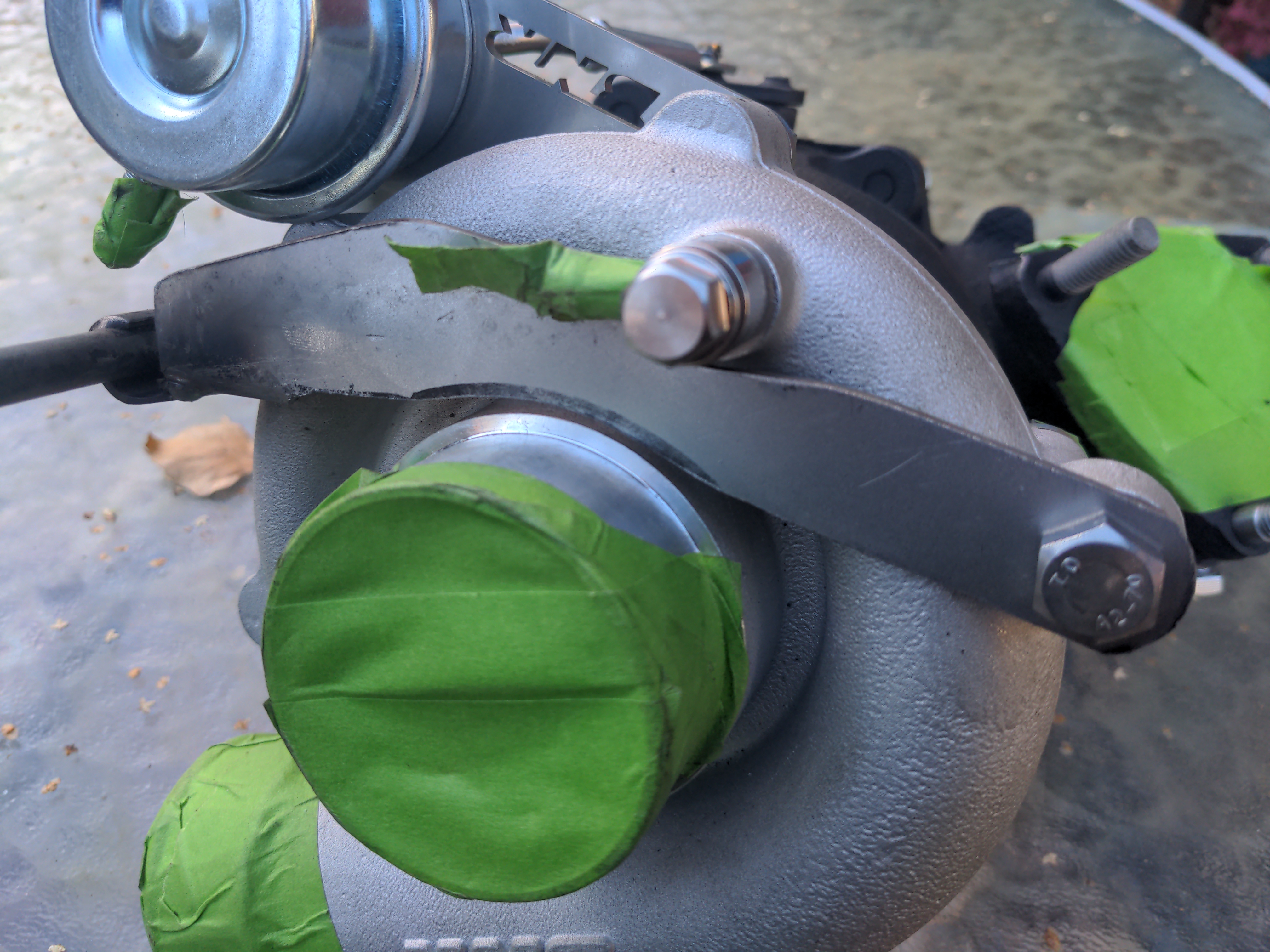
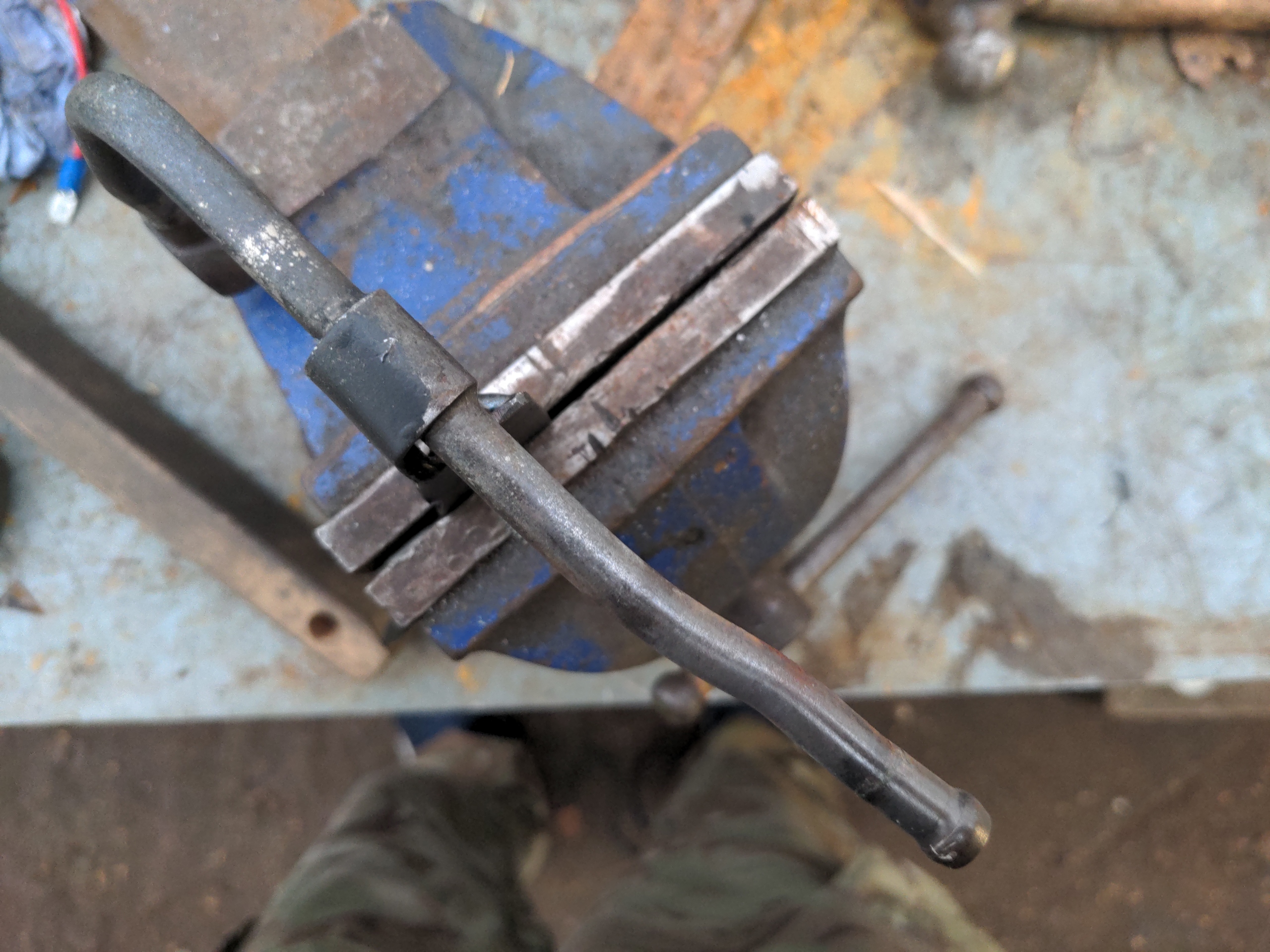
You strip the turbo down to this...
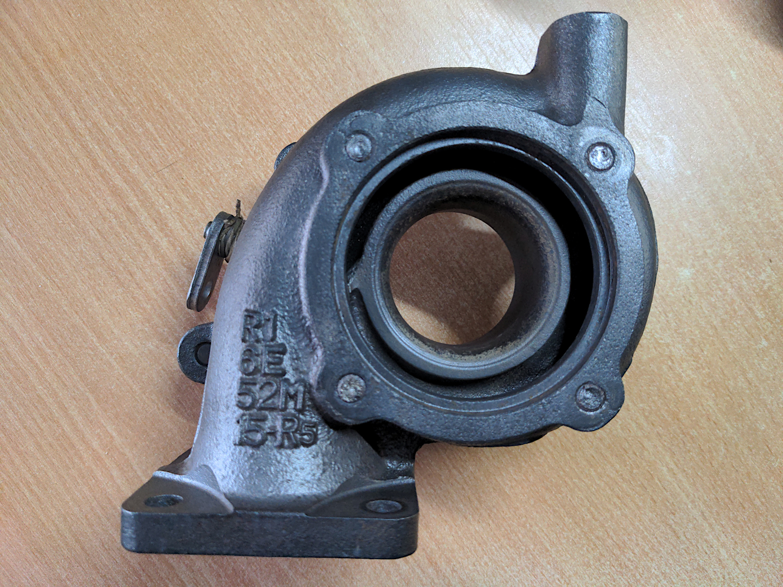
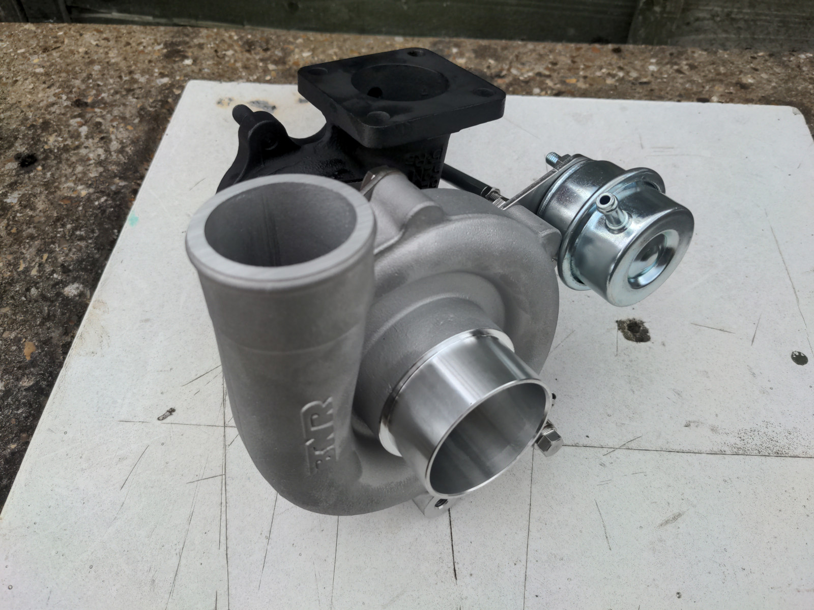
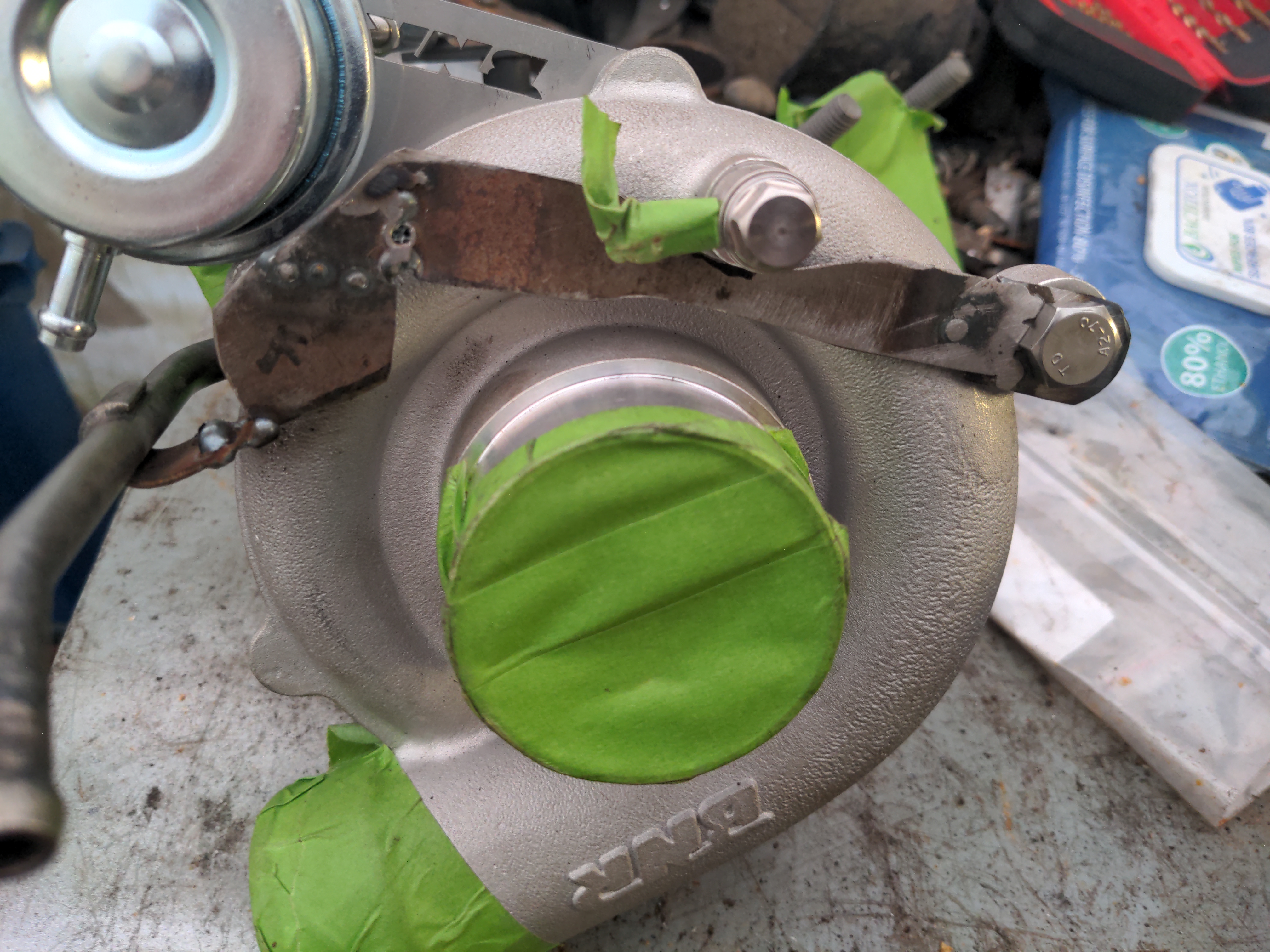
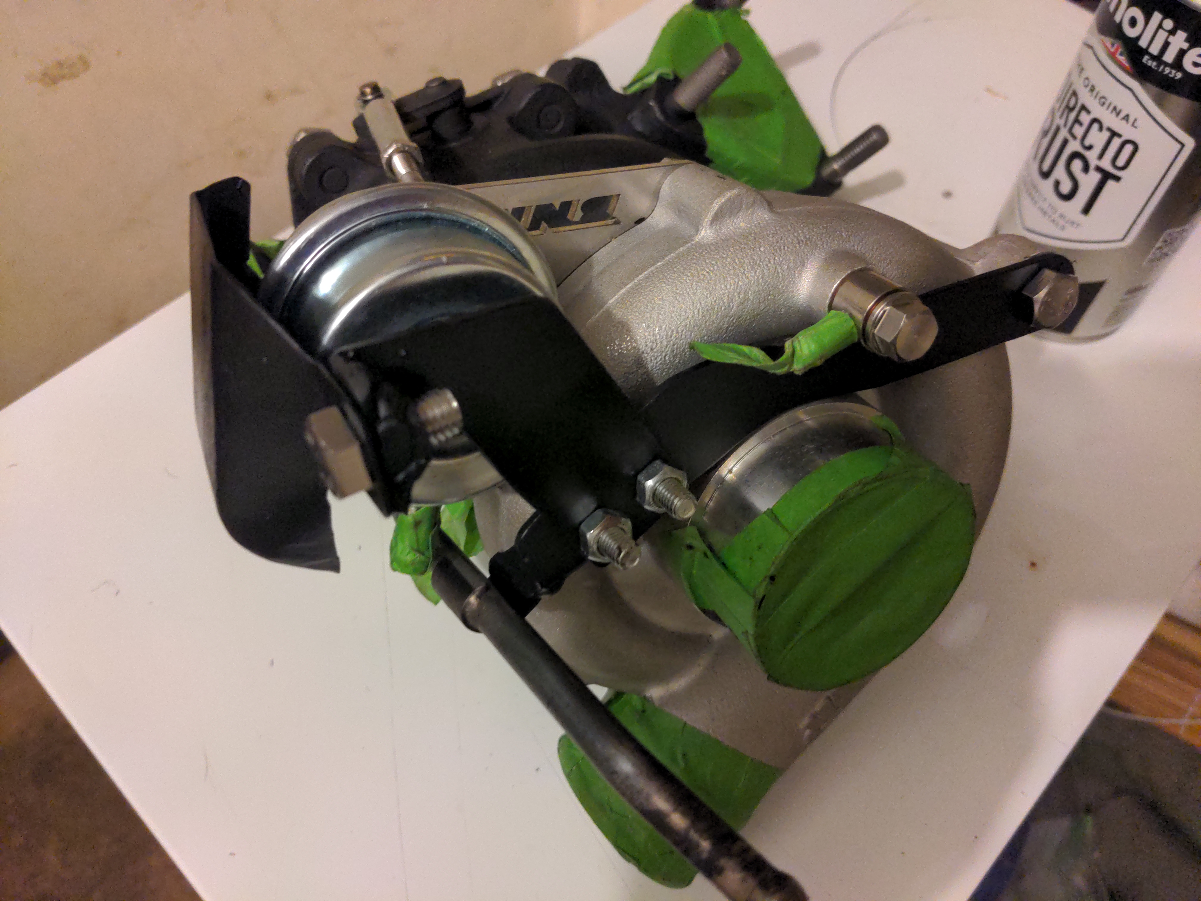
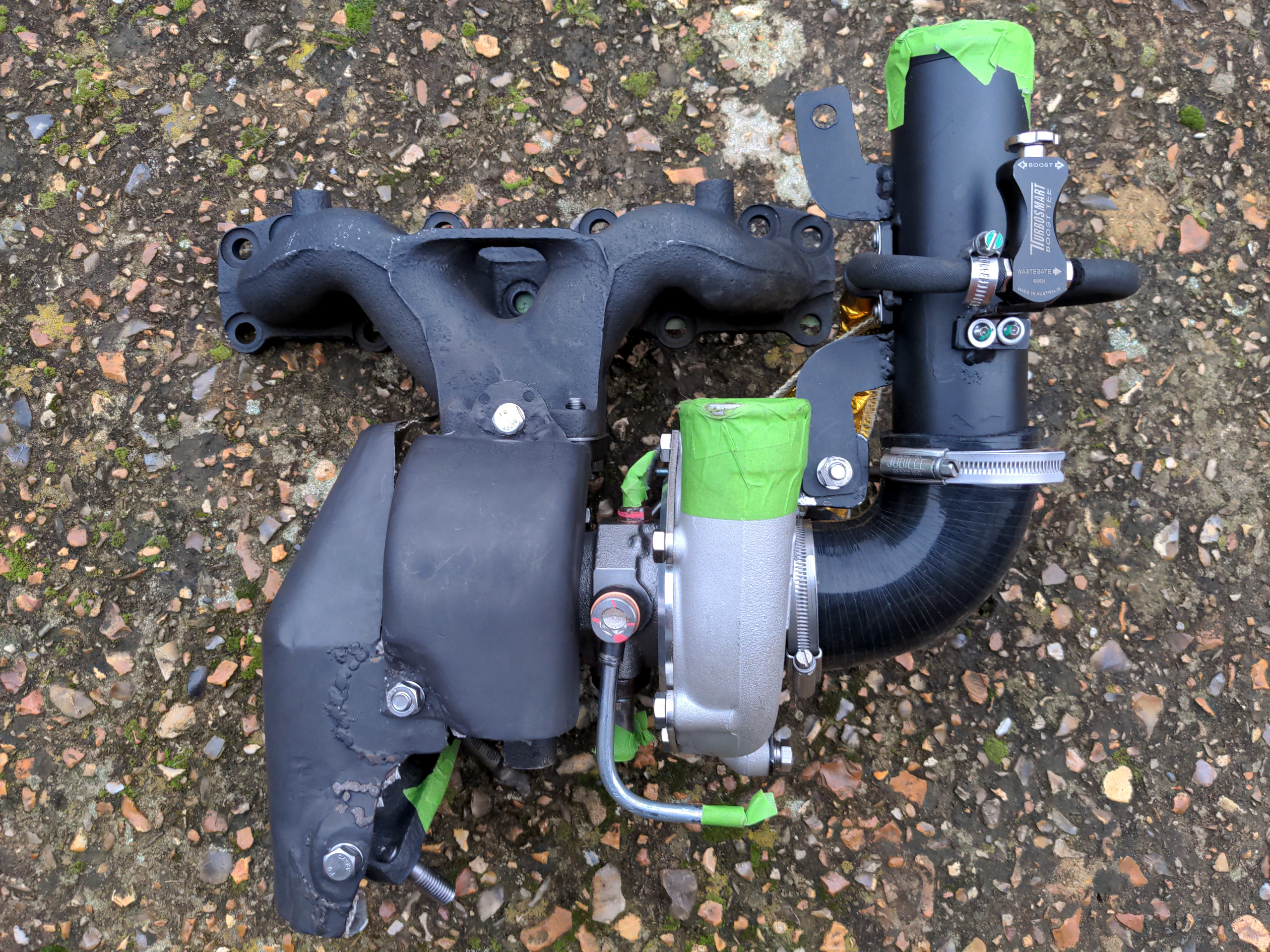
...post it to Alabama, then some time and about a grand later it comes back as this monster:
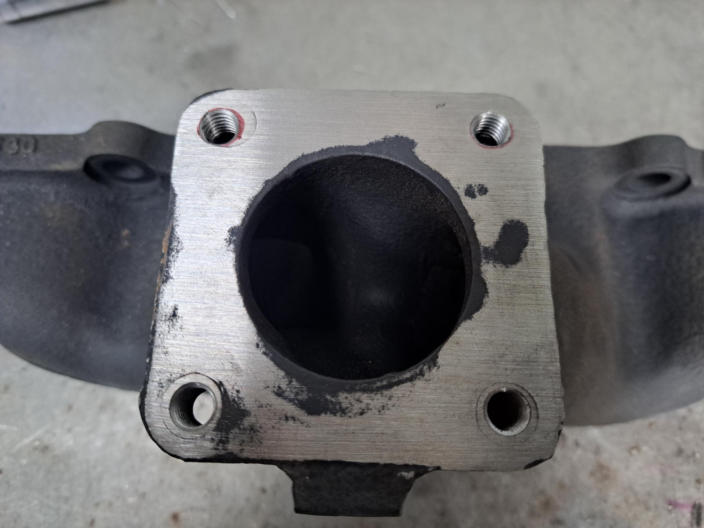
So, backtracking. The first pic is the turbine housing, and just the turbine housing. This bolts up to your exhaust manifold on one end, and bolts up to your downpipe on the other. Preserving this means that fitting this turbo does not require any modifications to the exhaust system; it stays as a bottom-mount turbo, bolting up to your original exhaust manifold and exhaust.
The rest of the turbo is thrown in the bin (don't actually do this, you'll need at least the compressor housing later as a reference for building pipework), and in its place you get a Garrett GT2860 CHRA with 360° thrust bearing, a much bigger compressor housing, an upgraded wastegate actuator, and a ported wastegate to avoid boost creep. Or, in other words, most of a modern Garrett GT2860 shoved inside half of an IHI VJ9!
All of that is balanced meticulously, turning a worn-out turbo that was never very good even when new into a modern, reliable turbo good for about 330 horsepower (which is about 130 more than I care to have, but I like having the option). This completely rules!! And it allows me to keep the bottom mount setup, with the same exhaust manifold & downpipe, and the same water and oil feeds. So all that was left was to just bolt it all together, and
JUST KIDDING THAT NEVER HAPPENS
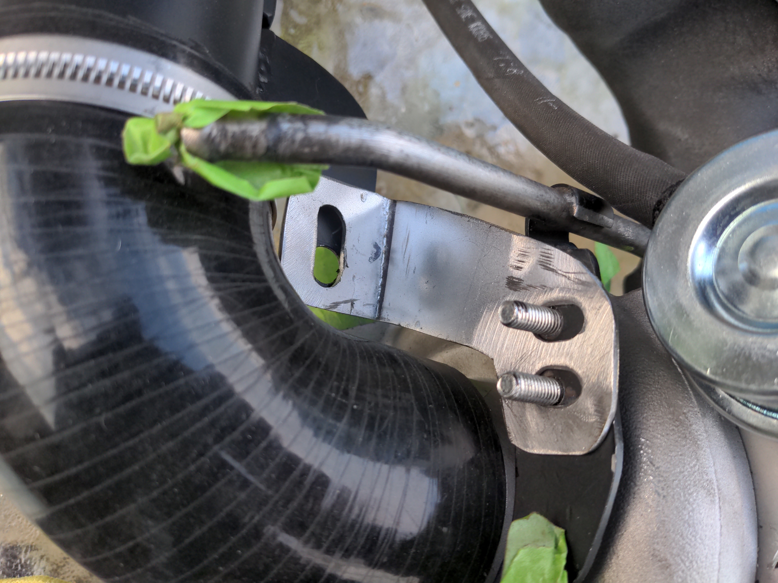
Of course I knew it would not be that simple. The cold-side intake of the new turbo being substantially larger than the VJ9 rather guaranteed that. So let's start with this intake pipe.
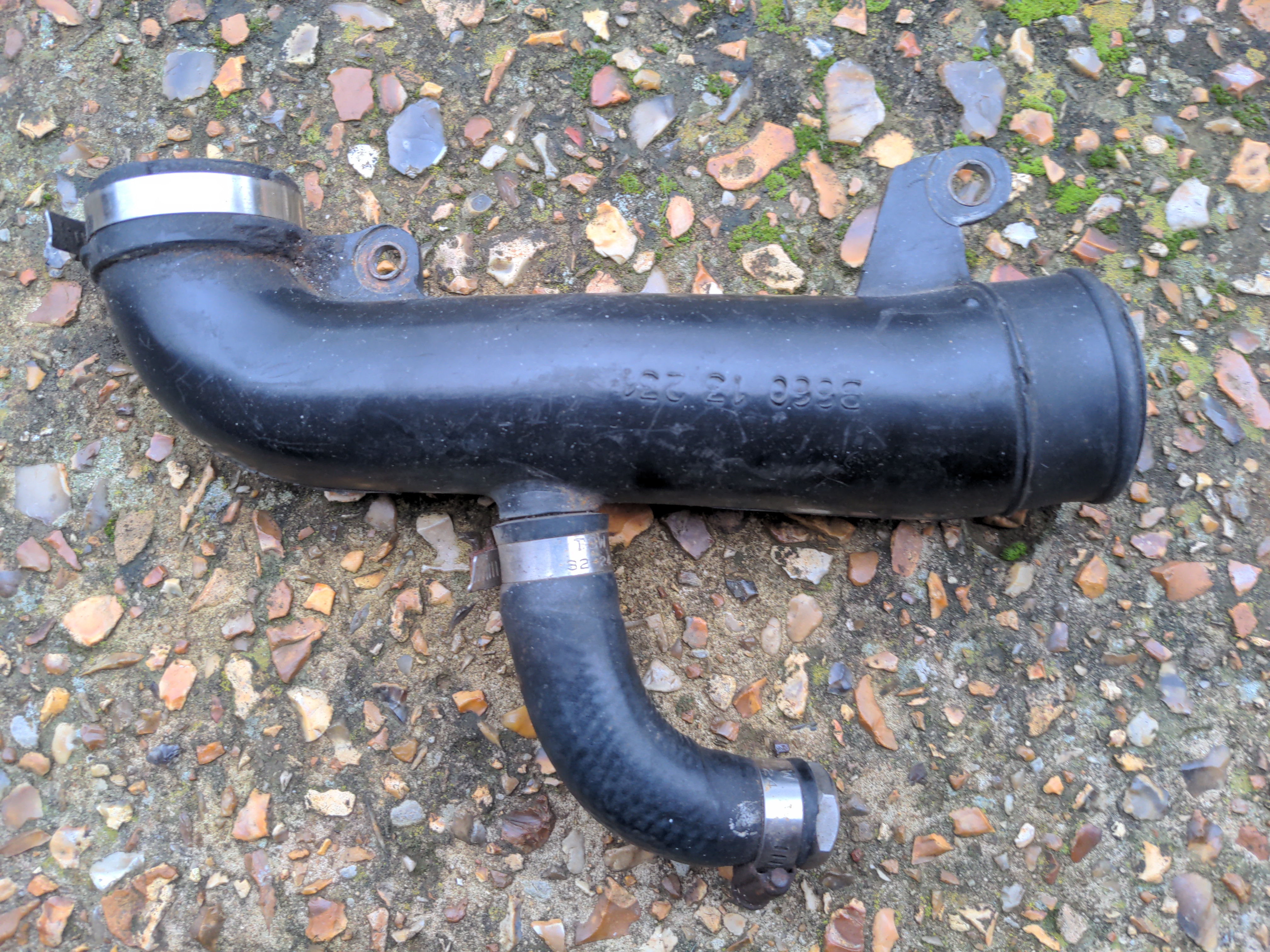
I can't modify this pipe, because it is made of plastic. Well, I could; that wouldn't be that much worse than at least one of the modifications I have seen in this engine bay (clue: it is in the photo above). But half of the rationalisation project is to remove bad modifications, and I do not want to add another.
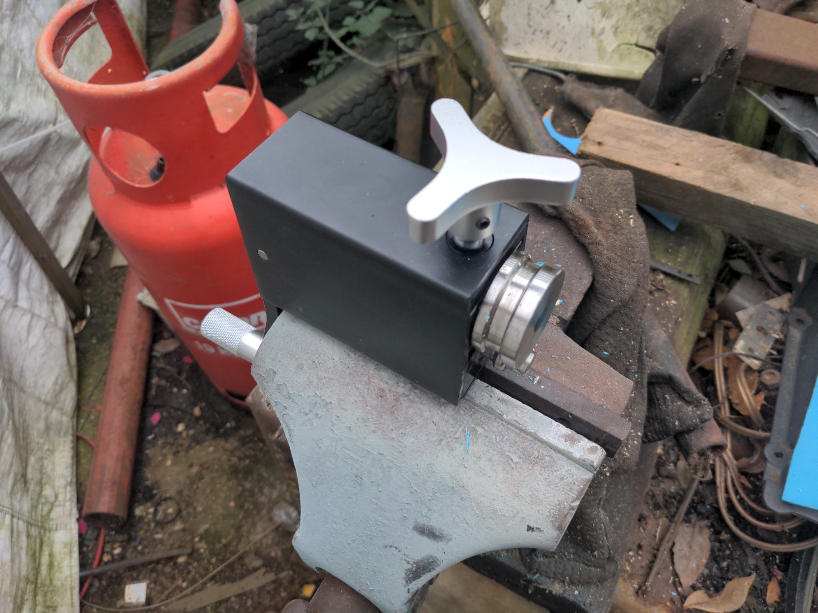
Finding someone who could fabricate a new intake pipe for turned out to be harder than it sounds (and this resulted in another multi-month delay), so I decided I might as well try and make it myself out of steel. And that starts with this:
(Richard Brunning voice) This may look like some pieces of wood screwed into a piece of wood. But what it actually is, is a jig for the intake pipe.
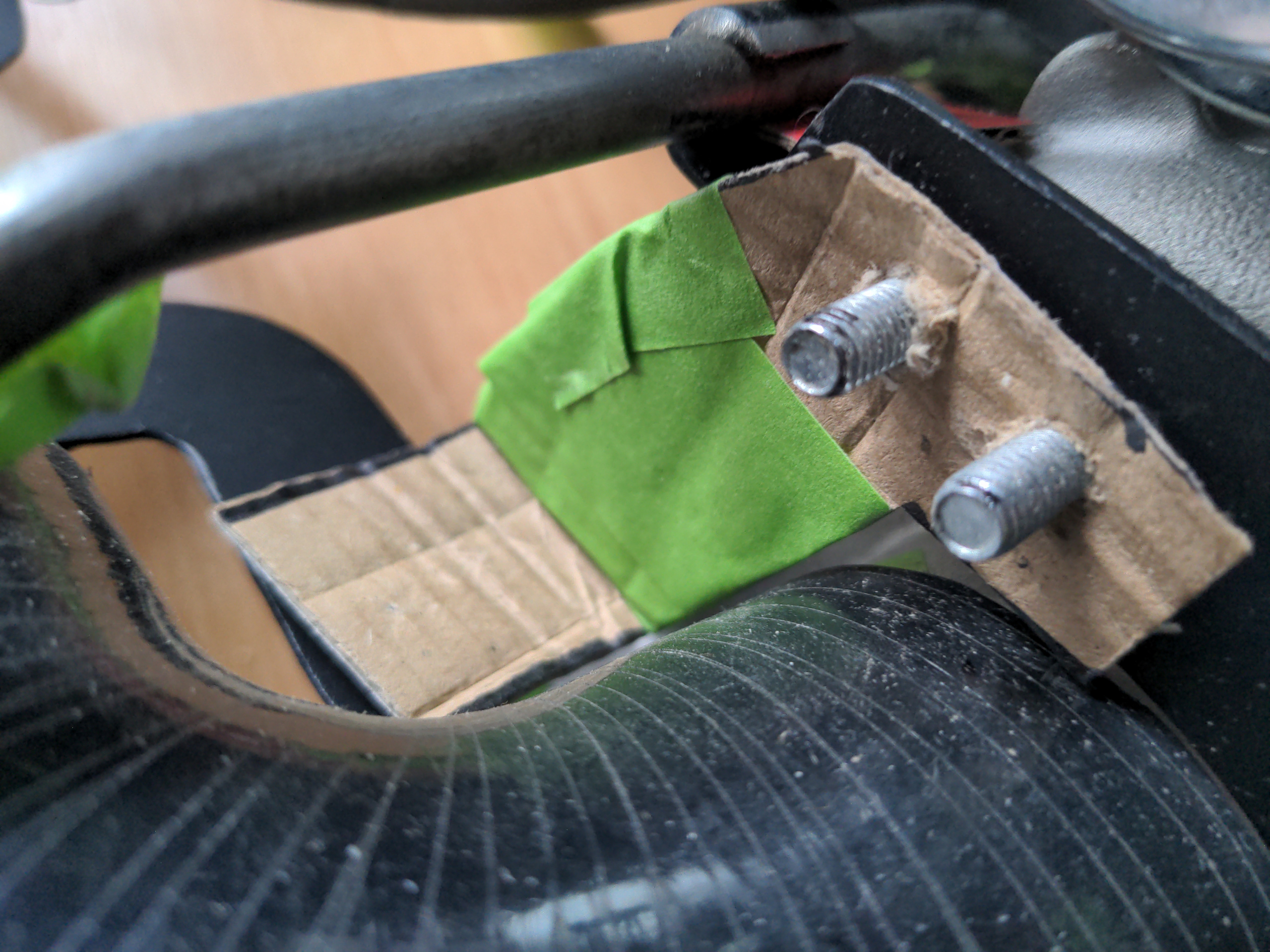
It marks out the rough locations of the inlet and outlet of the pipe, and it has some exhaust studs screwed into the wood which mark the location of the bolt holes. Some more pieces of wood mark the inlet and outlet of the pipe. All of this allows me to line up a piece of pipe (I happened to have an offcut of exhaust tubing which was exactly the right diameter for the job), and make some mounting points out of cardboard:
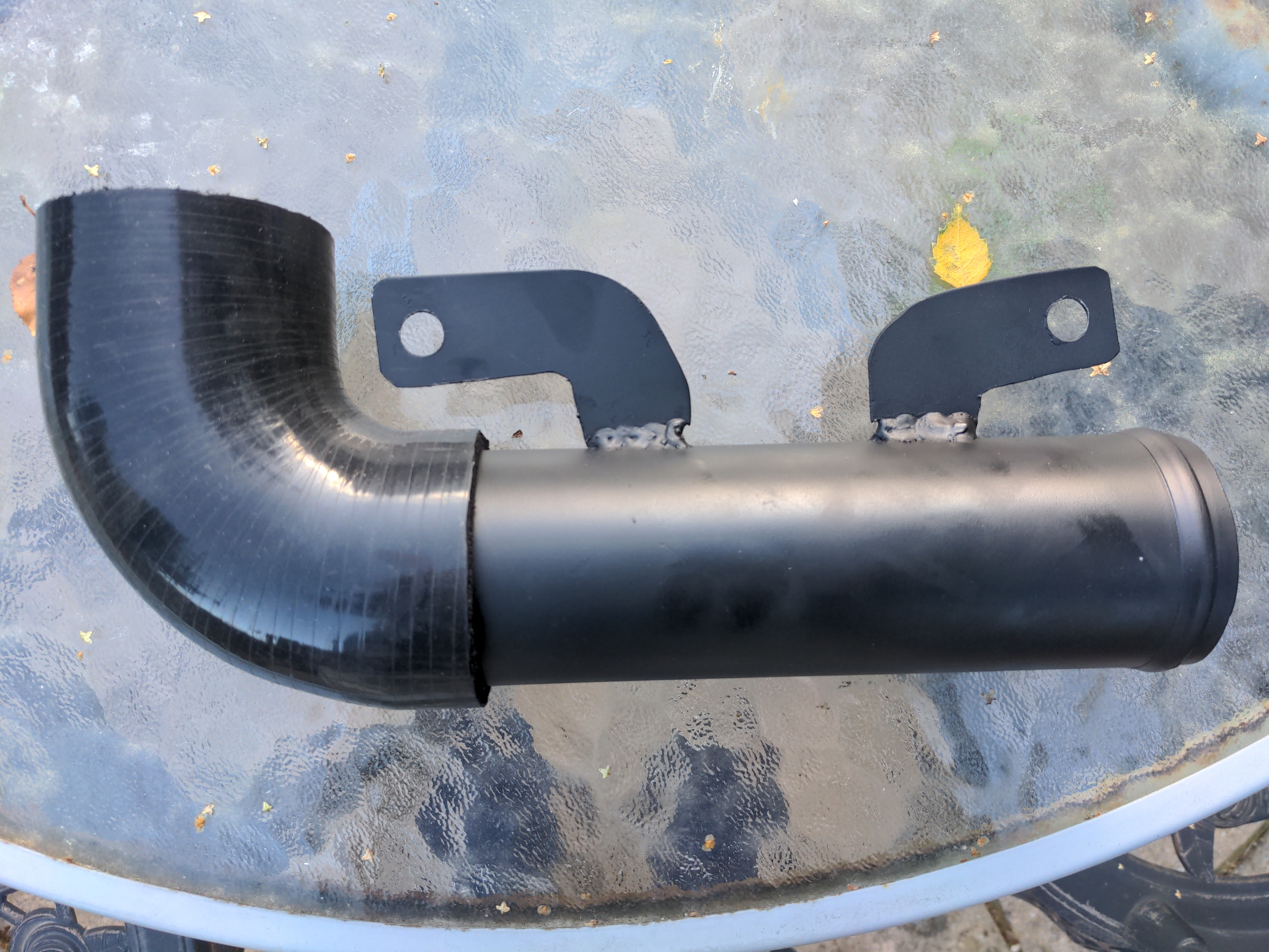
Those get made into 1.2mm steel with an angle grinder and welded on, and with a 90 degree silicone hose bend attached and a bit of Jenolite satin black paint...
...I have an intake pipe! And yes, I know those mounting points look like they are not fitted straight; I sacrificed this to get the mounting angle perfect. You'll live.
You may have noted the nice bead on the end of that pipe. I made that with a £70 hand-cranked bead roller. That was not a bad investment. It's easy to use; even I got it more-or-less right on my second attempt.
Meanwhile, the water feed pipe for the turbo used to have a bracket that bolted on to a mounting point on the turbo.
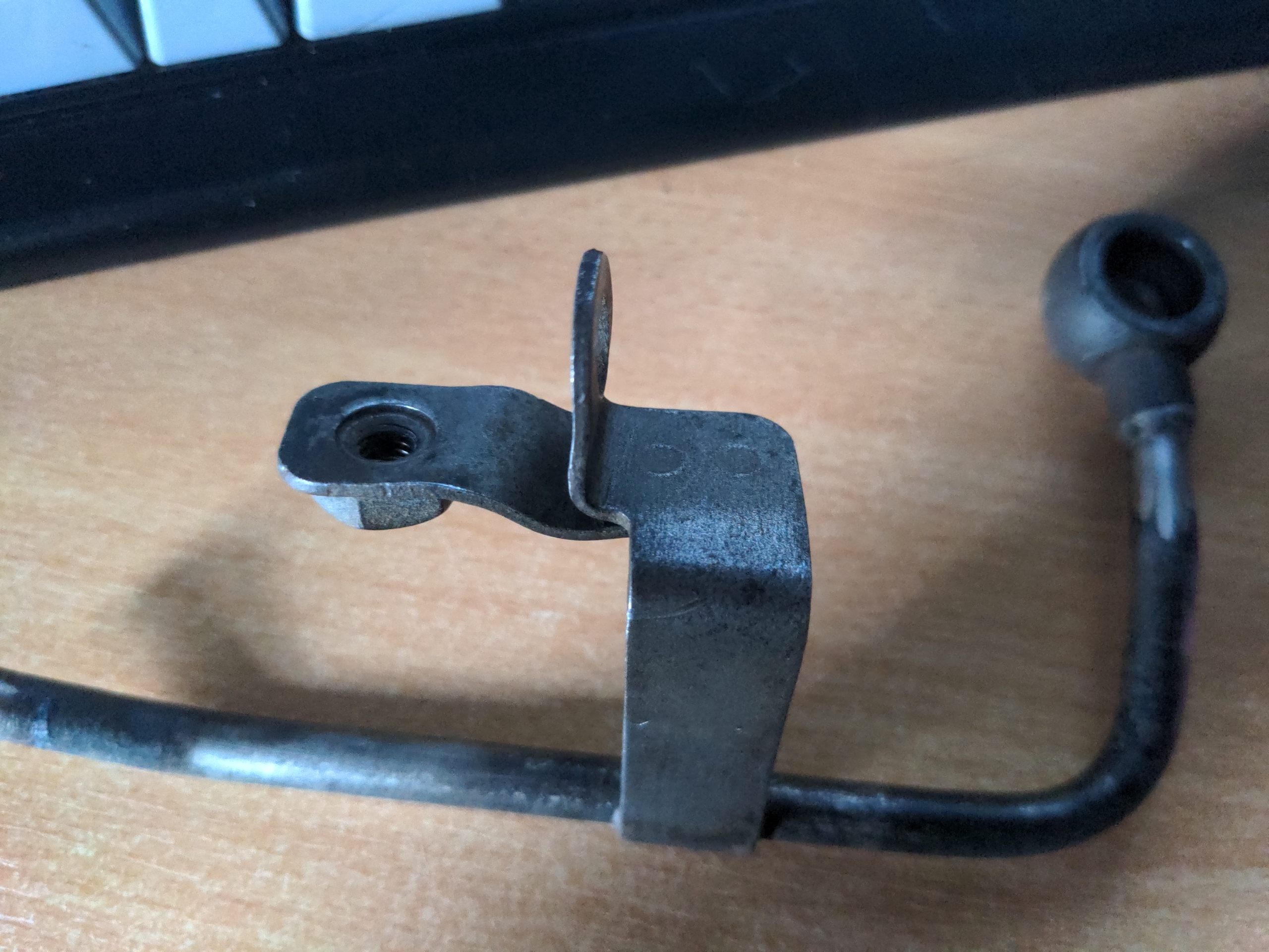
That mounting point does not exist on the new hybrid turbo. This bracket might have been overkill and I considered doing away with it altogether, but again I just assumed Mazda knew what they were doing when they did this, so made a prototype adapter bracket to go onto a mounting point on the compressor housing:
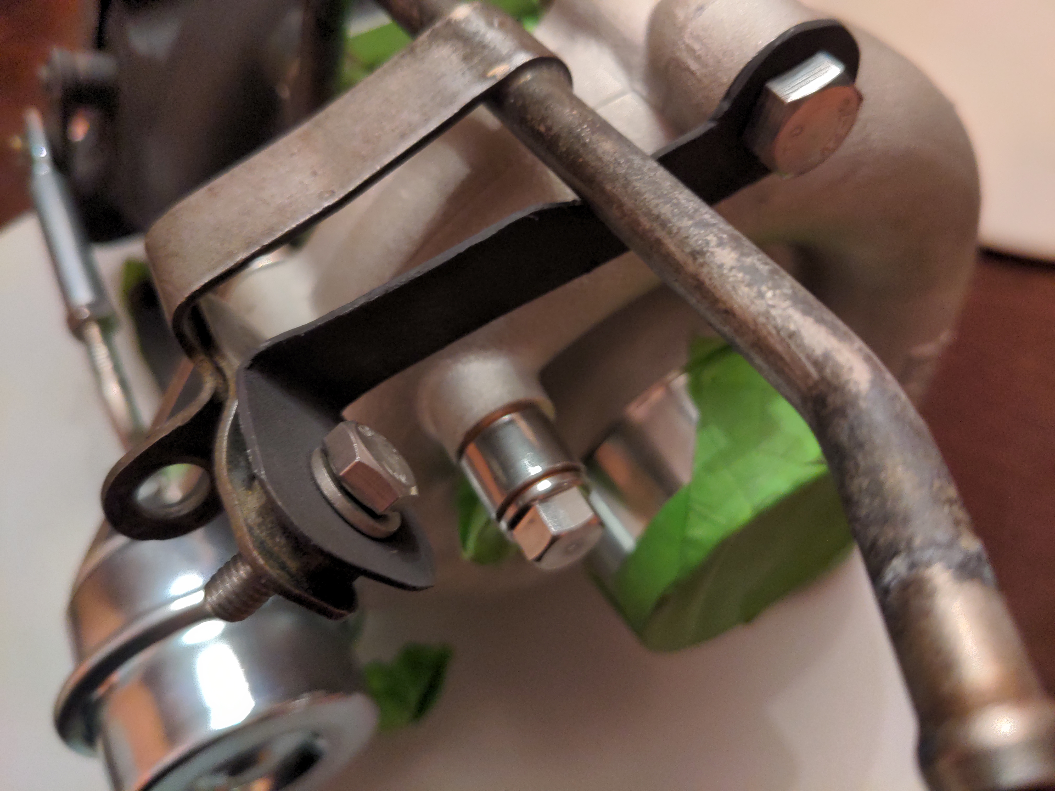
But after giving it some thought, I realised this would put the water pipe in the wrong orientation; it would feed from the correct side, but it would feed water up into the turbo, rather than down. That would be fighting gravity, which isn't such a big deal, but because it was fed from a completely different place, further modifications would be required on the engine side of all of this to make it work. I didn't want that, so I rethought it, chopped off the bracket from the water pipe, and welded on this crude prototype bracket made out of some 1mm scrap (also, see if you can spot where I forgot to turn on the MIG welder's gas)...
...before committing to it and making a preliminary version out of 2mm steel.
But then I realised that with a small modification to my original wastegate actuator heatshield...
...I could incorporate that into the assembly, by making another 2mm steel bracket to bolt on to it via some M6 captive bolts welded on to the water pipe bracket.

Which, when refined a little with a flappy wheel and painted in more satin black Jenolite paint, actually looks quite neat.
Meanwhile, here was my "boost controller".
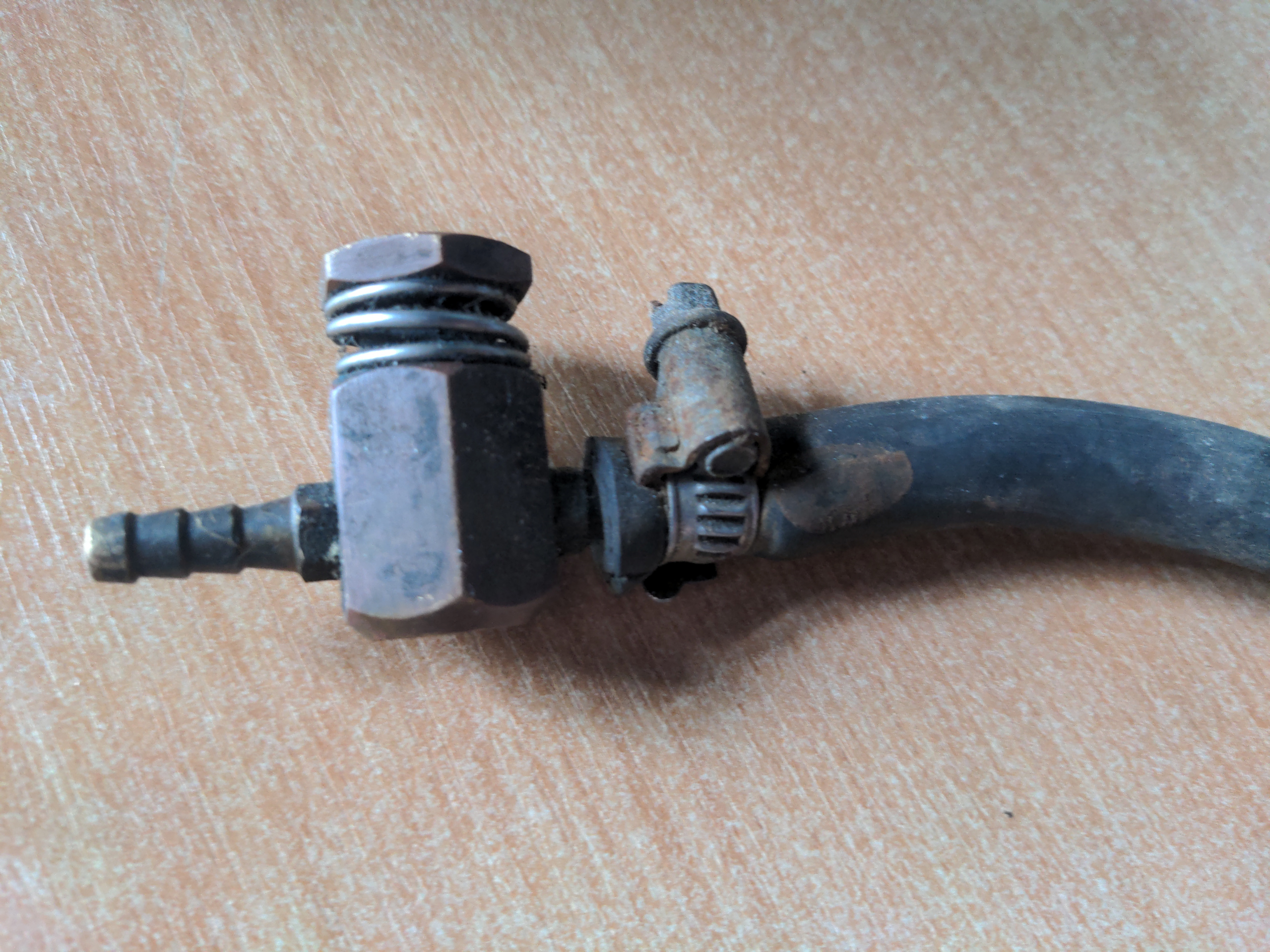
I put "boost controller" in quotes. My brother doesn't like it when I call it a boost controller; he insists that this is merely a bleed valve, and so I call it a boost controller to annoy him. It bleeds off air pressure to the wastegate, which means that the wastegate opens at a higher boost pressure. This is a very cheap way to run more boost in a turbo car. This did the job; it meant the 323 GTX was running about 13 psi, which with some calculations I completely made up would make it run about 200 horsepower.
Still, I didn't like this boost controller, which is why I put it in quotes. It dangled around the engine bay not attached to anything but its hoses; thus, it was a bad modification. So I spent a few quid on a new Turbosmart Boost-Tee manual boost controller, which probably does the same thing, but looks much better.
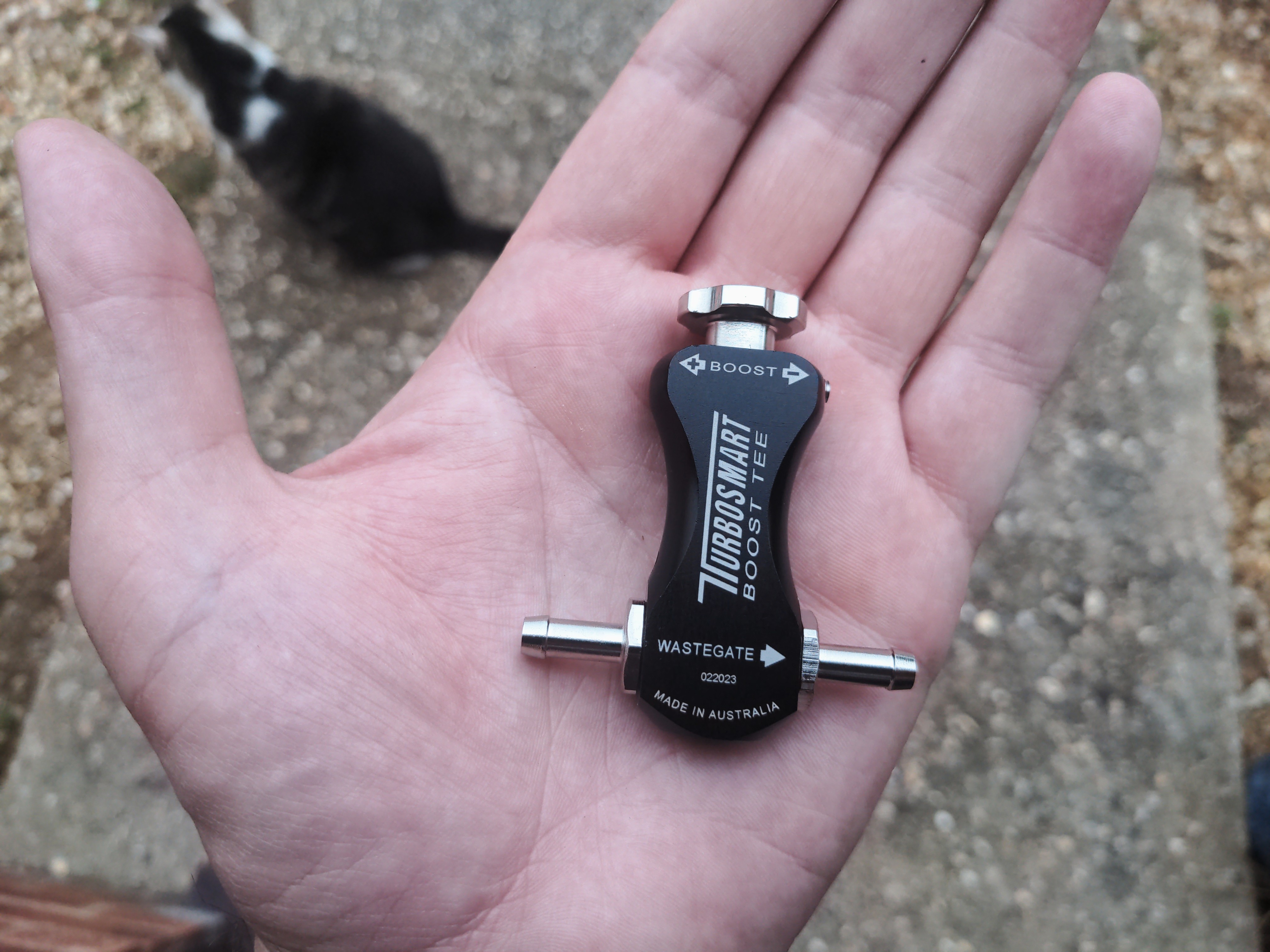
This controller came with a bracket to attach it somewhere, and I was not entirely sure where when I bought it. Most people would just shove it into the bodywork with self tappers or cable tie it somewhere; if I did that, it would be another bad modification. Instead, after looking at my nice new intake pipe I figured attaching it there might be a good idea. So I did!
I took a 5mm-ish-thick section of angle iron, chopped it into smaller bits of steel, drilled and tapped some M4 threads into it...
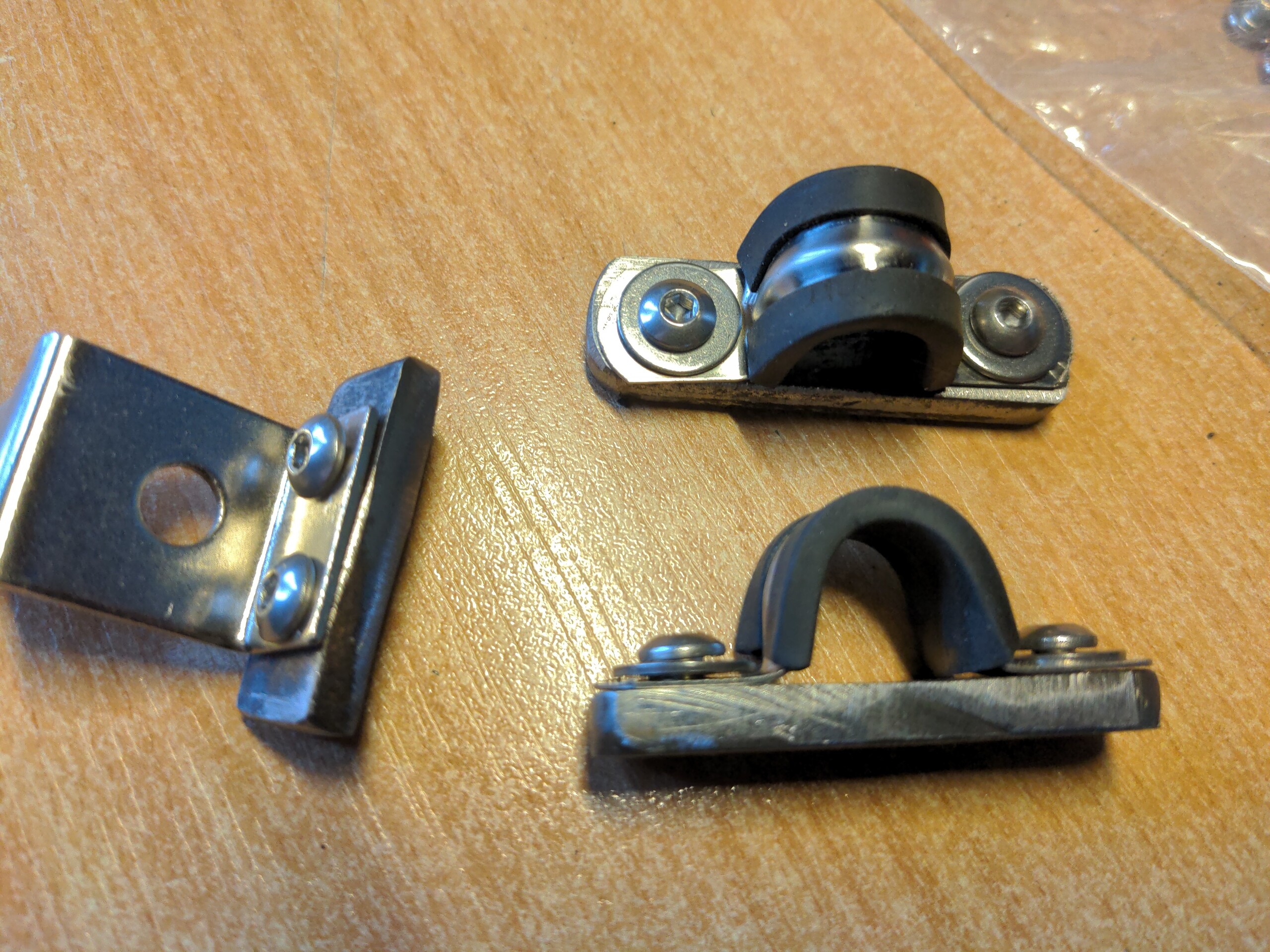
...and welded them on to my intake pipe to became the mounting points for both the pipe clamps and the boost controller.
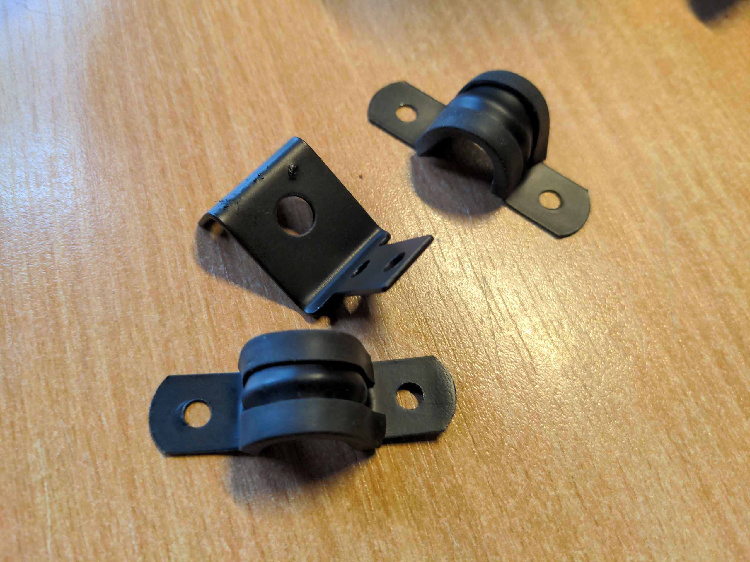
But, it bugged me that the boost controller bracket and the pipe clamps were shiny stainless steel, so I fixed that too, not that I am obsessed about tiny details or anything.
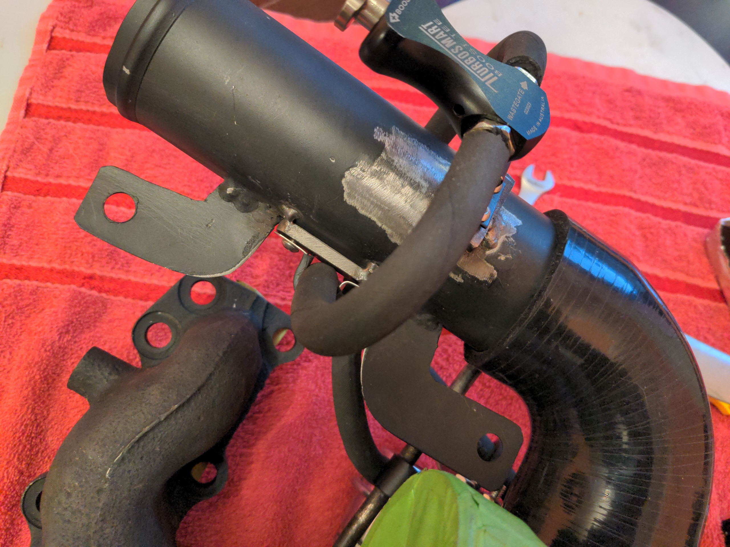
And then I modified the wastegate actuator heat shield bracket to add a routing guide for the pipe, which is to say, I drilled a hole in a piece of steel and welded that on to it.
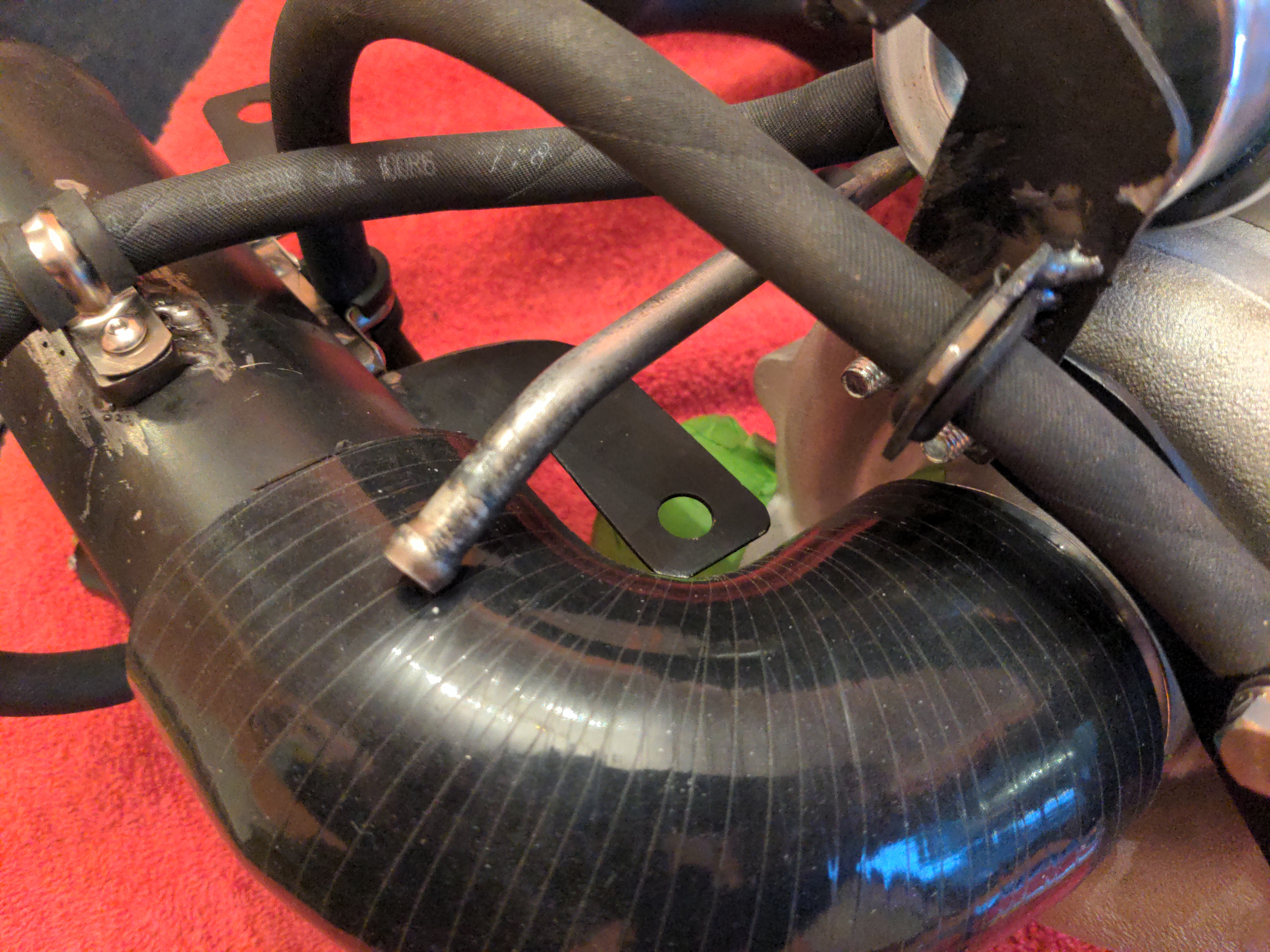
You may notice that the water pipe is uncomfortably close to the intake pipe. You'd be wrong, because it's actually touching, which is more than uncomfortably close. We'll fix this later!
Back to our intake pipe. Here is a photo of it, in case you forgot what it looks like.
The mounting point on the right hand side on this photo bolts onto the engine somewhere. The one on the left used to bolt on to the turbo, on a mounting point that no longer exists. Which is OK, because we can add another bracket to our combined water pipe & wastegate actuator heat shield bracket to make a three way bracket!11
That means making a rough template out of a previously-unseen proprietary composite material (Frogtape-reinforced cardboard)...
...then copying that on to 2mm steel...
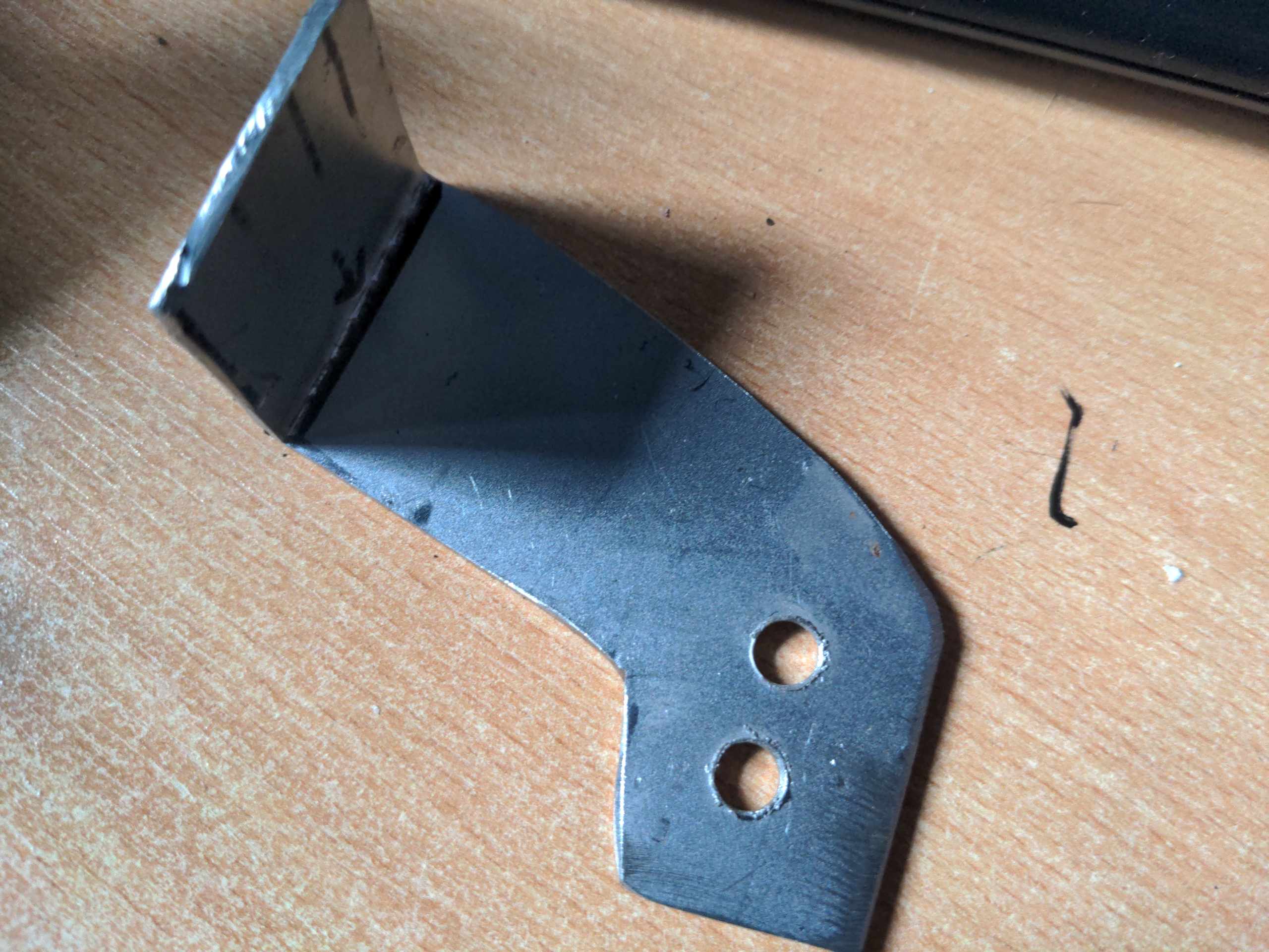
...then fine-tuning with a flappy wheel and other abrasive tools until it is a BRACKET.
If you didn't notice (and also if you did), the holes here are slotted on opposite axes (and doing this burned out my Ryobi multi-tool; lesson learned). This is because I am working blind, without the car; while I have taken as much care as I can to get this intake pipe dimensionally compatible with the original, I still don't know anything for a fact. With the combination of these slots, the flexible 90 degree bend, and the flex in the mounting points (the reason I made them out of 1.2mm steel!), this should have enough adjustment to fit on the car even if I got it completely wrong, which I don't think I did.
And now, some odds and ends, which happened at various points and didn't really fit into the narrative.
The downpipe and exhaust manifold were ceramic coated by my local powder coaters. This is an extremely high-temperature coating that should keep the heat in the exhaust system and out of the engine bay; as said previously, I am quite serious about heat management this time round.
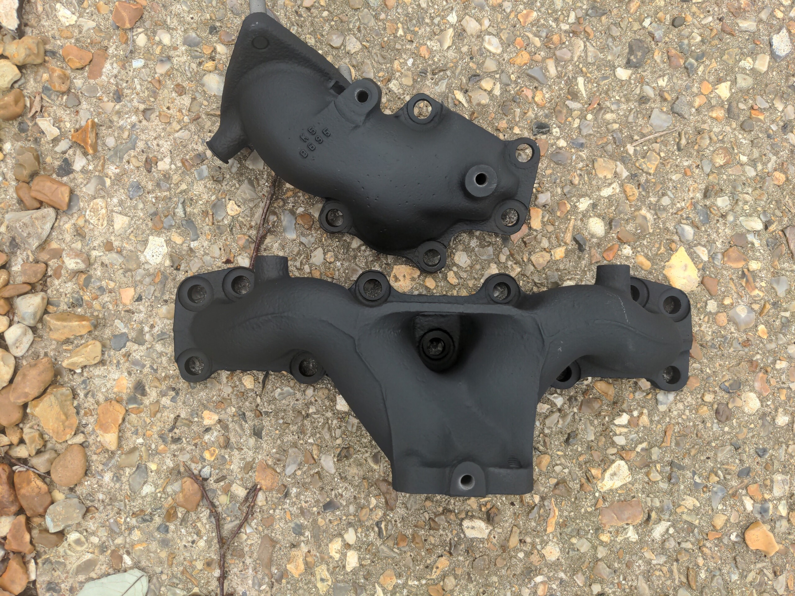
This could be great, or it'll lock the heat into the cast iron and cause it to fail spectacularly. We will see!
Talking of the exhaust manifold, several of the studs did not come out cleanly. I cut these off, and re-drilled them. But I made two huge mistakes. One of them I re-drilled ever so slightly away from where it should have been - maybe three quarters of a millimetre, which took it out of tolerance and meant that the turbo did not fit on it. With another of these, the hole clearly needed helicoiling, and I made the mistake of not using a drill press when drilling it out for the helicoil. I figured the existing hole would guide me well-enough to be able to do it with a hand drill, and no it did not guide me well-enough; the hole for the helicoil was not made straight, and this meant the stud did not go in straight.
I thought this would be a write-off for the manifold, because nobody wants to fix 36 year old cast iron. Except Matt from Fusion Fabrications! Who drilled all but one of the holes out to 12mm, forced in some cast iron bungs, then meticulously re-drilled all the holes at the correct spacing.
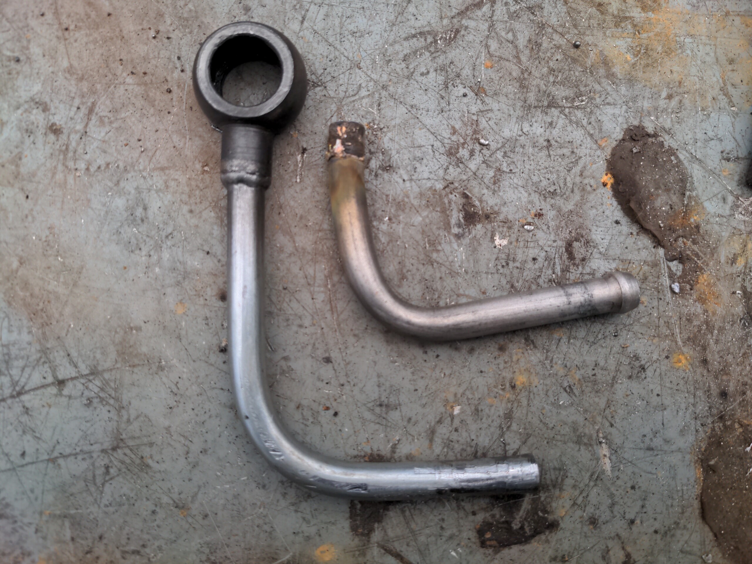
Back to that water feed pipe from earlier. This only needed a tiny modification to get it to clear the much-larger intake pipe; I heated it up with the oxy-propane torch, and bent it in the other direction using two long sockets either side of the original bend.
The oil drain should have been a straight bolt-on fit. The Garrett CHRA was drilled to have them as two M6 holes spaced 38mm centre-to-centre. This is the correct spacing for every RHB5 turbo. But the drain from my VJ9 was spaced at 40mm for no reason, because why wouldn't you randomly have one turbocharger in a range of turbochargers with a subtly different oil drain?? Which means, it does not fit. So, the holes on the original oil drain had to be slotted 1mm inwards (thanks Maurice).
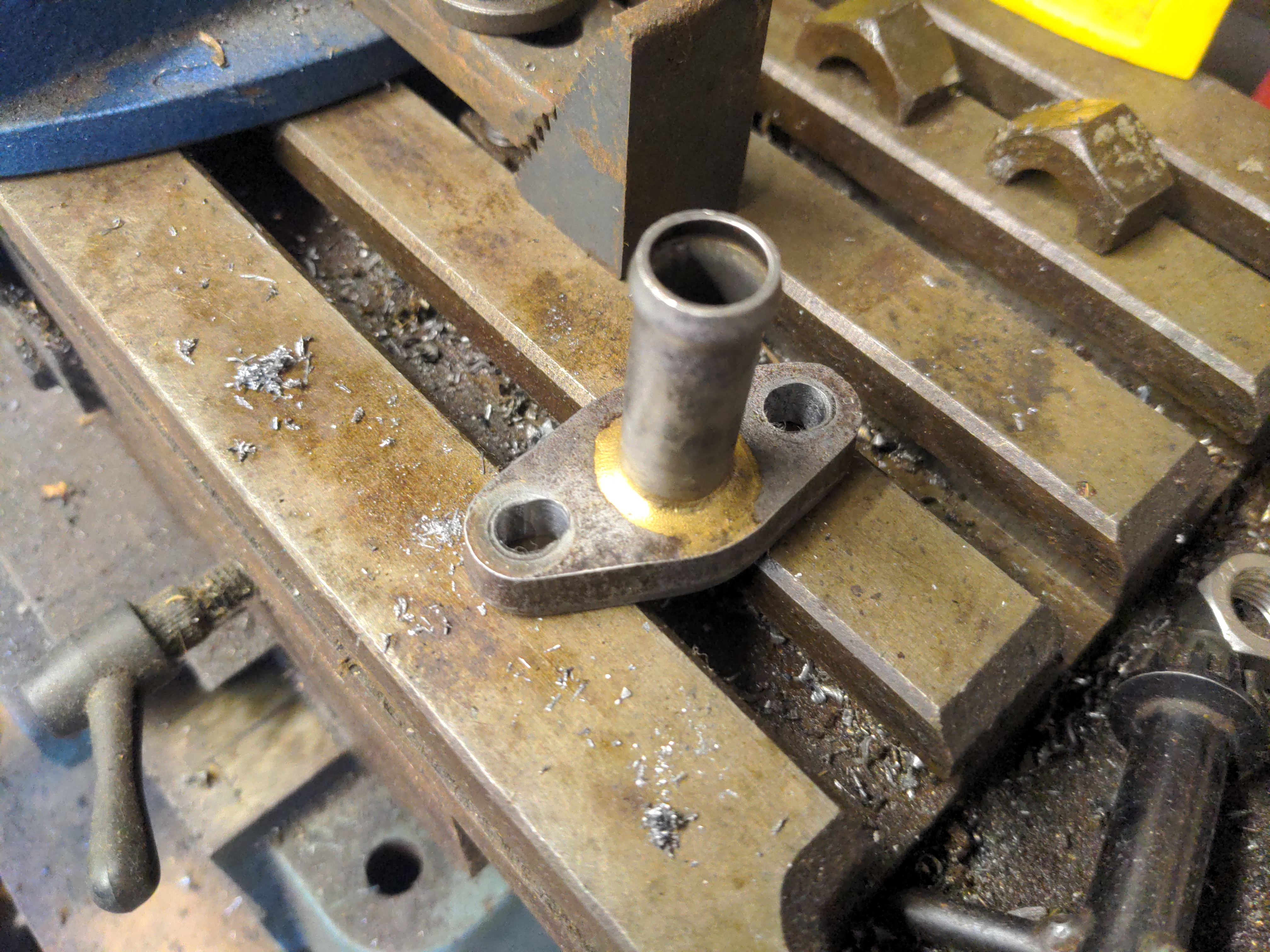
And finally, the water drain pipe was not long enough to clear the much bigger turbine housing. So that was remade using the original banjo fitting.
And so, thirteen months later, it is Done; all that is left is to drive it and all the other new bits over to my engine builder tomorrow.
The turbo itself is a massive upgrade. The ceramic coatings & improved heat shielding should also be a substantial upgrade, and the new boost controller is not a bad modification like the old one was. And it looks a whole lot less ugly, though it is likely that nobody but me and my engine builder are ever going to see any of this.
More than anything, though, this has been a massive confidence boost for me. After having so many supplier delays (accounting for about nine of the thirteen months when you factor in people who gave me radio silence), I figured I'd take a punt at doing as much as I could of the work myself, such as the brackets & pipework & boost controller mounting. In one case doing it myself didn't work out; I should not have taken such a cavalier approach to the exhaust manifold studs, and I am thankful for Matt for fixing my mess. But sometimes it actually worked out fine! The pipework & brackets work well enough, and that was mostly just me and an angle grinder and a worn-out MIG welder.
So, back to that Rover P5...